
Thermo-acoustic nuclear power distribution measurement assembly

a technology of nuclear power distribution and measurement assembly, which is applied in the direction of instruments, nuclear elements, greenhouse gas reduction, etc., can solve the problems of high cost of replacement power, complicated refueling process of top mounted instruments, etc., and achieve the effect of high propensity

Active Publication Date: 2014-12-11
WESTINGHOUSE ELECTRIC CORP
View PDF5 Cites 2 Cited by
  • Summary
  • Abstract
  • Description
  • Claims
  • Application Information

AI Technical Summary

Benefits of technology

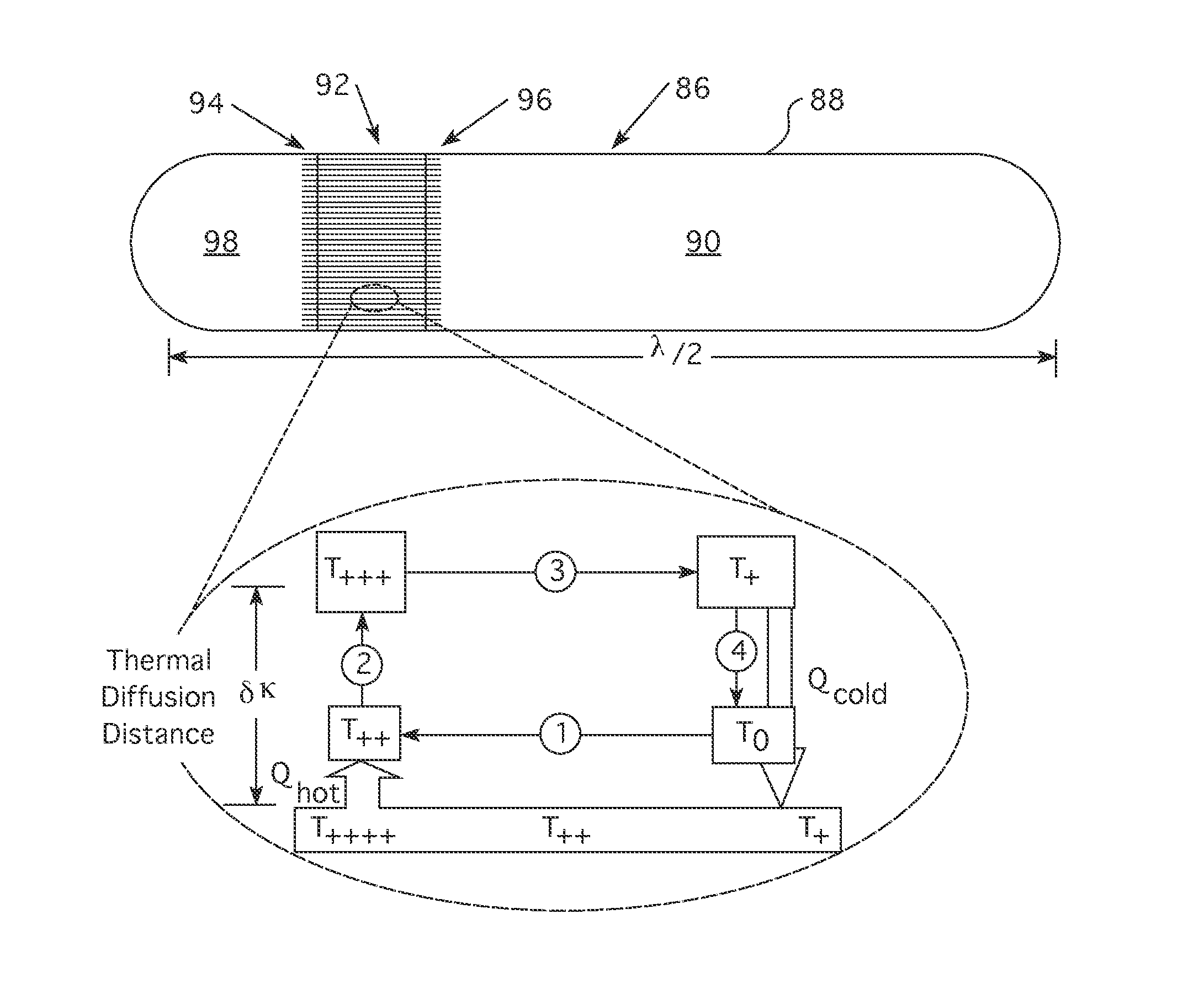
The invention is a thermo-acoustic nuclear power distribution measurement assembly that includes multiple thermo-acoustic engines in a spaced tandem array. The assembly is designed to fit within the instrument thimble of a nuclear fuel assembly. Each engine has a self-sustaining heat source and a resonant chamber that generates sound waves based on the temperature difference between two locations within the chamber. The cladding of each engine is highly thermally conductive to coot the gas within the chamber. The assembly includes spacers to thermally insulate each engine's heat source from an adjacent engine, and an acoustic telemetry system to receive the sound waves generated by the engines. The assembly can be located within the fuel assemblies of a nuclear power generation system. The technical effects include improved accuracy and reliability of temperature measurement and improved safety and reliability of the nuclear power generation system.

Problems solved by technology

However, the top mounted instrumentation complicates the refueling process, because these sensors have to be removed from the core before the fuel assemblies can be accessed for relocation or replacement.
Conserving outage time to a utility operator is a critical objective, because of the high cost of replacement power incurred during an outage.

Method used


Image

  • Thermo-acoustic nuclear power distribution measurement assembly
  • Thermo-acoustic nuclear power distribution measurement assembly
  • Thermo-acoustic nuclear power distribution measurement assembly

Examples


Embodiment Construction

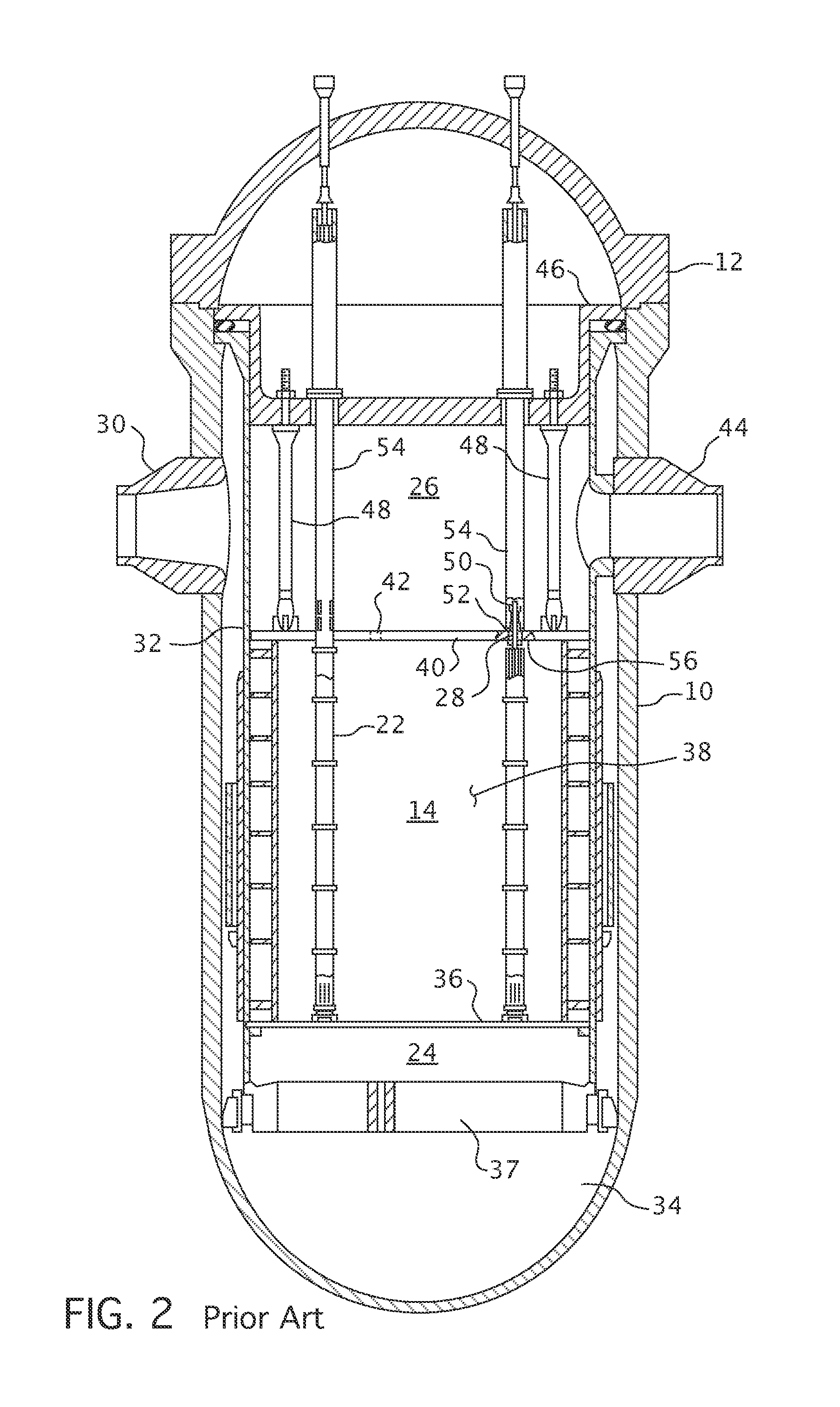
[0027]The performance of a nuclear reactor, like that of many other energy conversion devices, is limited by the temperature which component materials will tolerate without failure. In the case of a nuclear reactor with the core comprising an assemblage of fuel assemblies, such as the one illustrated in FIG. 3, the upper limit of temperature is determined by the fuel rod or fuel pin cladding materials employed. In order to adequately protect the reactor core against excessive temperatures, it is necessary to examine the temperature of the “hottest” fuel pin or the “hottest” coolant channel between adjacent fuel pins in the core, since damage will most likely first occur in the hottest fuel pin. Thus, the “hottest” pin or channel becomes the limiting factor for safe reactor core operation.

[0028]As is well known, heat is generated in a reactor by a fission process in the fuel material. The fission process, however, produces not only heat but radioactive isotopes which are potentially ...


PUM


Abstract

A nuclear power distribution measurement assembly that is sized to fit within an instrumentation thimble of a nuclear fuel assembly, that employs a spaced tandem arrangement of thermo-acoustic engines, each of which has a heat source side that is insulated from the reactor coolant traversing the nuclear core in which the fuel assembly is to be placed and a cold side housing a resonator chamber with enhanced thermal conductance to the coolant. The resonator chamber of each of the thermo-acoustic engines is of a different length to generate a different frequency whose amplitude is proportional to the neutron activity at the axial and radial position of the thermo-acoustic engine. The frequency identifies the measurement assembly's position. Acoustic telemetry is employed to monitor the acoustic waves generated by the individual thermo-acoustic engines to provide a remote reading of the axial and radial power distribution of a reactor core.

Description

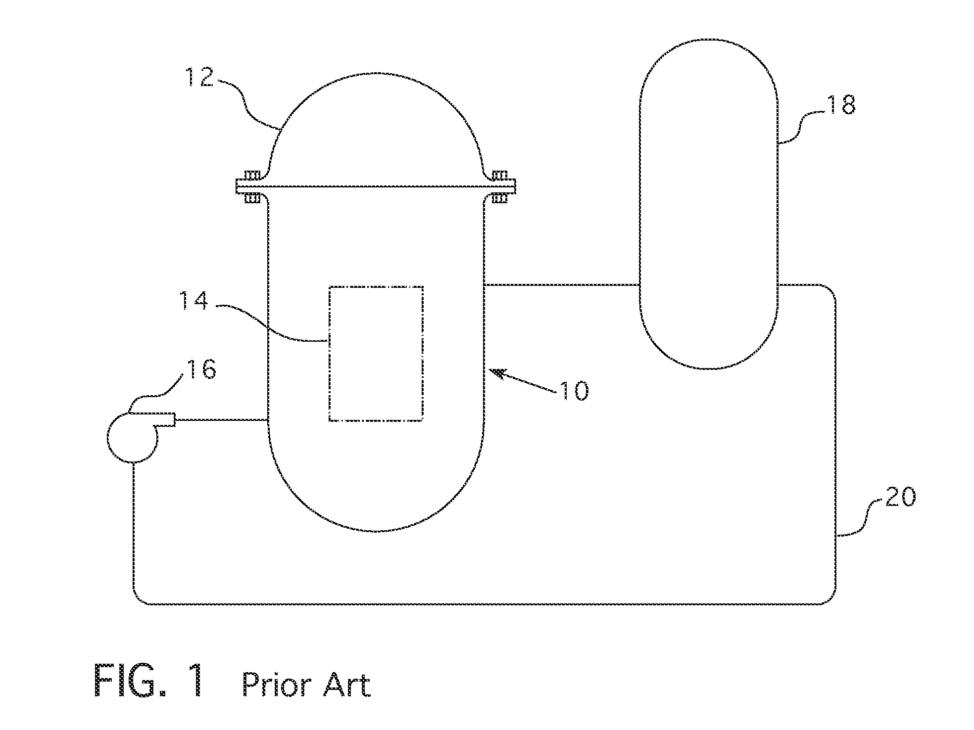
CROSS REFERENCE TO RELATED APPLICATION[0001]This application is a continuation-in-part application of and claims priority to U.S. patent application Ser. No. 13 / 869,159, filed Apr. 24, 2013, entitled THERMO-ACOUSTIC NUCLEAR POWER DISTRIBUTION MEASUREMENT ASSEMBLY.BACKGROUND[0002]1. Field[0003]This invention pertains generally to nuclear reactor monitoring systems and more particularly to an in-core power distribution monitor.[0004]2. Related Art[0005]The primary side of nuclear reactor power generating systems which are cooled with water under pressure comprises a closed circuit which is isolated in heat exchange relationship with a secondary circuit for the production of useful energy. The primary side comprises the reactor vessel enclosing a core internal structure that supports a plurality of fuel assemblies containing fissile material, the primary circuit within heat exchange steam generators, the inner volume of a pressurizer, pumps and pipes for circulating pressurized water; ...

Claims


Application Information

Patent Timeline
Patent Type & Authority Applications(United States)
IPC IPC(8): G21C17/10G21C17/104
CPCG21C17/104G21C17/102G21C17/112G01N29/036G01N29/222G01N2291/02881G21C17/108G01N29/032G01N2291/014G01N2291/015G21C17/10Y02E30/30G01N29/22
Inventor HEIBEL, MICHAEL D.FLAMMANG, ROBERT W.SUMEGO, DAVID M.
Owner WESTINGHOUSE ELECTRIC CORP
Learn More