Processes for producing substrate for liquid ejection head

a technology of liquid ejection head and substrate, which is applied in the direction of printing, electrical equipment, electric discharge tubes, etc., can solve the problems of increasing the size of the chip, and achieve the effect of increasing the chip size and lowering the productivity

Active Publication Date: 2014-12-11
CANON KK
View PDF2 Cites 2 Cited by
  • Summary
  • Abstract
  • Description
  • Claims
  • Application Information

AI Technical Summary

Benefits of technology

[0005]According to the process disclosed in Japanese Patent Application Laid-Open No. 2009-137155, the independent liquid supply port is formed in the bottom of the common liquid supply port by the dry etching. However, the process causes a phenomenon called tilt, by which the independent liquid supply port is formed slantingly depending on the three-dimensional shape of the common liquid supply port. When the tilt is markedly caused, the opening position of the independent liquid supply port in a front surface of the substrate greatly deviates from a desired position, so that reliability is lowered to cause a possibility that the chip size is increased. Thus, an object of the present invention is to provide a process for producing a substrate for a liquid ejection head, by which the occurrence of tilt can be inhibited without lowering productivity.

Problems solved by technology

When the tilt is markedly caused, the opening position of the independent liquid supply port in a front surface of the substrate greatly deviates from a desired position, so that reliability is lowered to cause a possibility that the chip size is increased.

Method used


Image

  • Processes for producing substrate for liquid ejection head
  • Processes for producing substrate for liquid ejection head
  • Processes for producing substrate for liquid ejection head

Examples


example 1

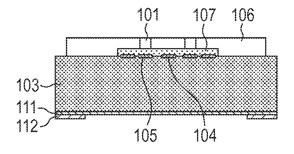
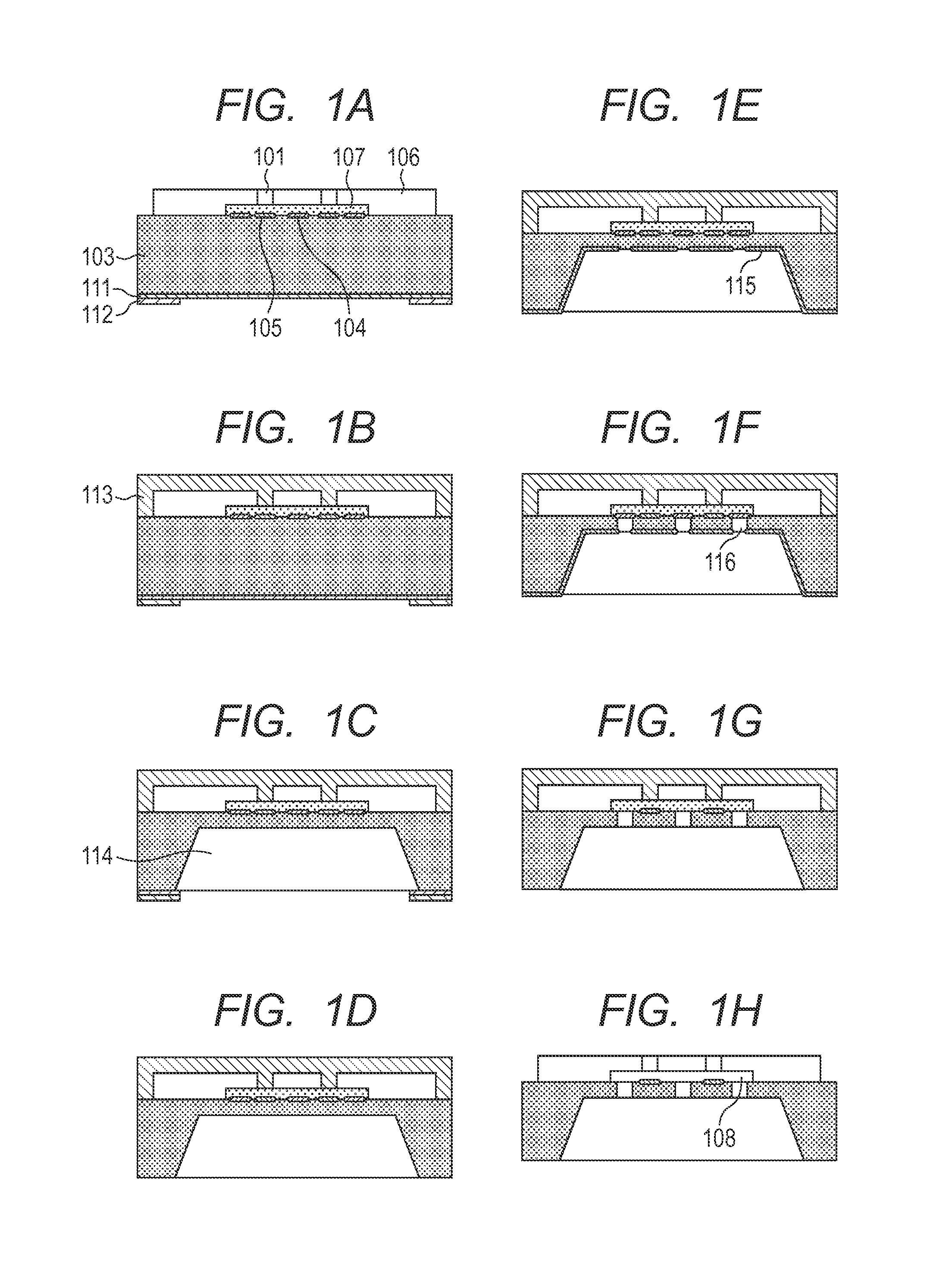
[0032]A process for producing a substrate for a liquid ejection head according to this example will now be described with reference to FIGS. 1A to 1H. A silicon substrate 103 having a thickness of 700 μm as illustrated in FIG. 1A was first provided. On a front surface of the silicon substrate 103, an ejection-energy-generating element 105, an etch-stop layer 104 and an insulation layer (not illustrated) formed on the ejection-energy-generating element 105 and the etch-stop layer 104 are arranged. The etch-stop layer 104 was formed by forming an aluminum film having a thickness of 500 nm by sputtering. The insulation layer was formed by forming an oxidized film having a thickness of 700 nm by plasma CVD. In addition, an adherence layer (not illustrated), a positive resist 107 and an ejection-orifice-forming member 106 are formed on the side of the front surface of the silicon substrate 103 for subsequently forming a liquid flow path wall and a liquid ejection orifice. The adherence l...

example 2

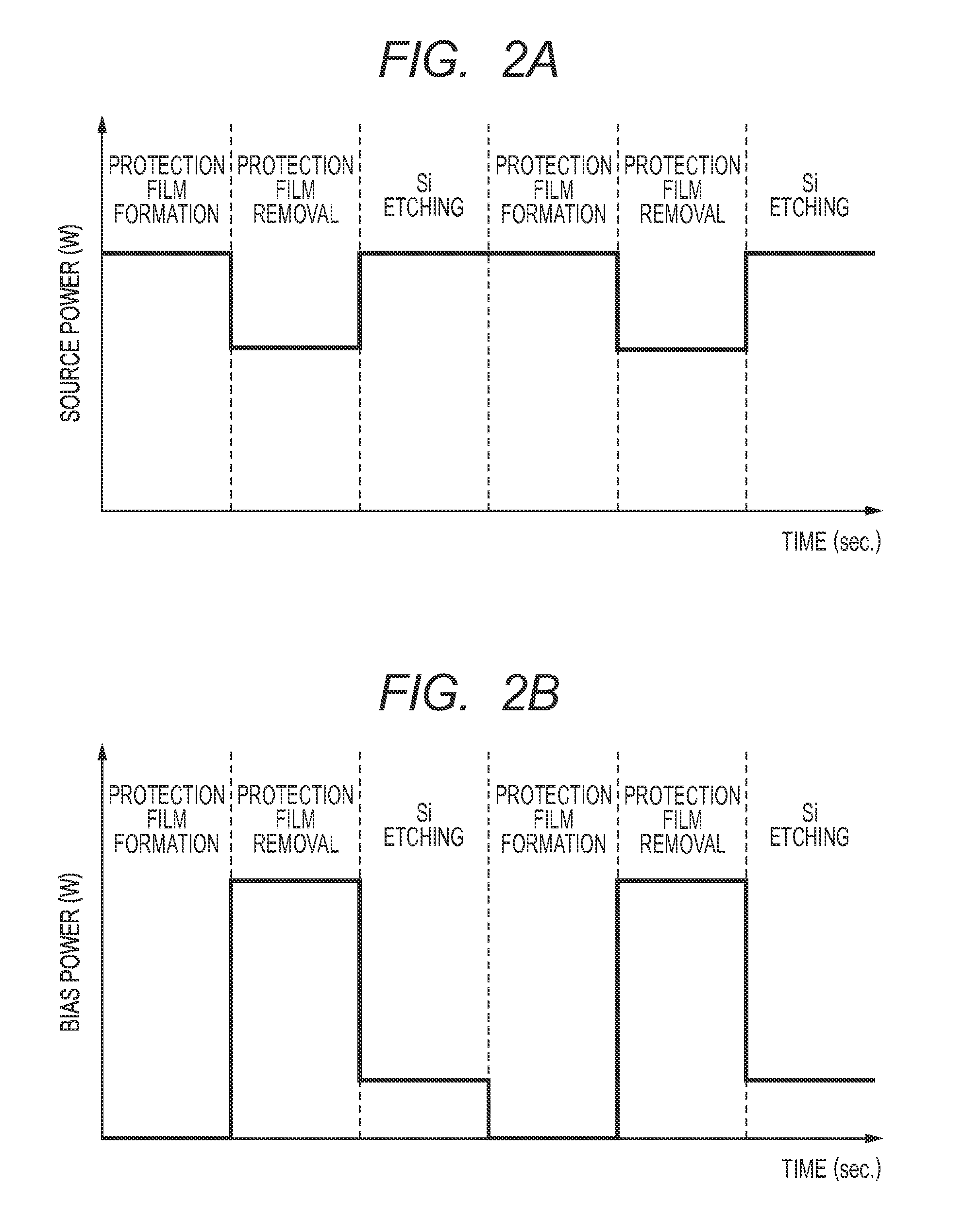
[0036]A substrate for a liquid ejection head was prepared in the same manner as in Example 1 except that the conditions in the respective steps of the Bosch process were changed to the conditions shown in Table 2. The reduction rate of the source power in the protection film removing step with respect to the source power in the Si etching step was 45%. The relation between the thicknesses of the sheaths was determined by means of the Child-Langmuir Law from the relation between the source powers. As a result, the sheath formed in the protection film removing step was thicker than the sheath formed in the Si etching step. The tilt of the independent liquid supply port of the thus-obtained substrate for the liquid ejection head was measured. As a result, the tilt was about 1.5 m.


PUM


Abstract

A process for producing a substrate for a liquid ejection head, including a step of forming a liquid supply port passing through a silicon substrate by dry etching, the step being a step of sequentially repeating the steps of (1) forming an etching protection film on the silicon substrate, (2) removing a bottom portion of the etching protection film, and (3) etching the silicon substrate, wherein a sheath formed in the step (2) is thicker than a sheath formed in the step (3).

Description

BACKGROUND OF THE INVENTION[0001]1. Field of the Invention[0002]The present invention relates to a process for producing a substrate for a liquid ejection head.[0003]2. Description of the Related Art[0004]As methods for forming a liquid supply port in a substrate for a liquid ejection head, a method of using drilling, laser beam machining or sand blasting, a method of forming a liquid supply port by anisotropic etching and a method of forming a liquid supply port by dry etching have been proposed. Among these methods, the method of forming the liquid supply port by the dry etching using an etching gas can form a liquid supply port of an almost vertical form, so that a chip size can be made smaller than the method of forming the liquid supply port by the anisotropic etching. Regarding the method of forming the liquid supply port by the dry etching, Japanese Patent Application Laid-Open No. 2009-137155 discloses a process in which a common liquid supply port is formed from the side of...

Claims


Application Information

Patent Timeline
Patent Type & Authority Applications(United States)
IPC IPC(8): B41J2/16
CPCB41J2/1648B41J2/1603B41J2/1628B41J2/1631B41J2/1639B41J2/1642B41J2/1646H01J37/32935
Inventor SAKAI, TOSHIYASUKATO, MASATAKAKUMAMARU, KENJI
Owner CANON KK
Why Eureka
Try Eureka