
Low-temperature gas supply device, heat transfer medium-cooling device, and low-temperature reaction control device

Inactive Publication Date: 2014-12-18
TAIYO NIPPON SANSO CORP
View PDF3 Cites 2 Cited by
  • Summary
  • Abstract
  • Description
  • Claims
  • Application Information

AI Technical Summary

Benefits of technology

The present invention provides a gas supply device and a heat transfer medium-cooling device that use low-temperature gas refrigerant. The device can efficiently mix two gases with similar temperatures and avoid pulsatile changes in flow, resulting in stable temperature control. The device also allows for easy adjustment of the intended temperature of the refrigerant and enables stable control of the temperature of the heat transfer medium without freezing it. The invention is also suitable for controlling the reaction temperature in a reaction vessel and can achieve stable control within a broad temperature range.

Problems solved by technology

This is because the heat transfer medium freezes and blocks a flow channel, and there is a case where the heat transfer medium cannot be circulated.
Also, when the heat transfer medium freezes and blocks a flow channel, the loss of pressure increases; therefore a pump having greater quality than design quality is needed, heat intrusion from the pump increases, and thus the usage of the low-temperature-liquefied gas for cooling increases.
Therefore, the low-temperature quality, which the heat transfer medium potentially has, could not be sufficiently used.
However, in simple mixing equipment, there is a problem in that the temperature of the low-temperature-liquefied gas becomes uneven and pulsative after mixing.
For example, a temperature of a liquefied nitrogen is greatly different from that of nitrogen gas of room temperature and because the liquefied nitrogen has large cold energy in a small flow, a control of a very little flow is difficult and after mixing, there is a problem in that a flow of the low-temperature-liquefied nitrogen gas becomes pulsative or a temperature becomes uneven due to poor mixing.
In order to solve the problems, for example, as disclosed in Patent document 3, efficient or large mixing equipment is needed, which incurs cost increases.

Method used


Image

  • Low-temperature gas supply device, heat transfer medium-cooling device, and low-temperature reaction control device
  • Low-temperature gas supply device, heat transfer medium-cooling device, and low-temperature reaction control device
  • Low-temperature gas supply device, heat transfer medium-cooling device, and low-temperature reaction control device

Examples


first embodiment

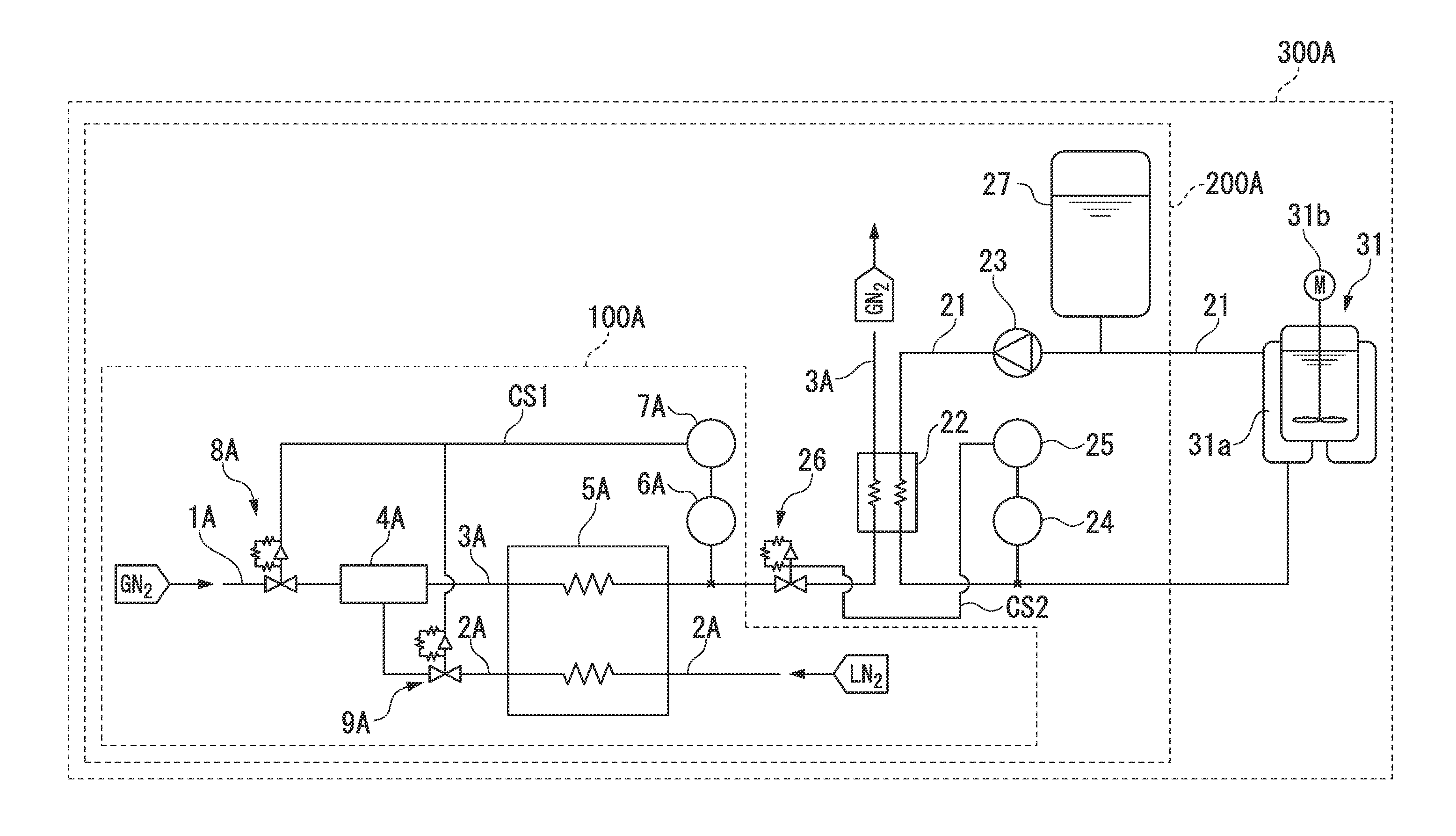
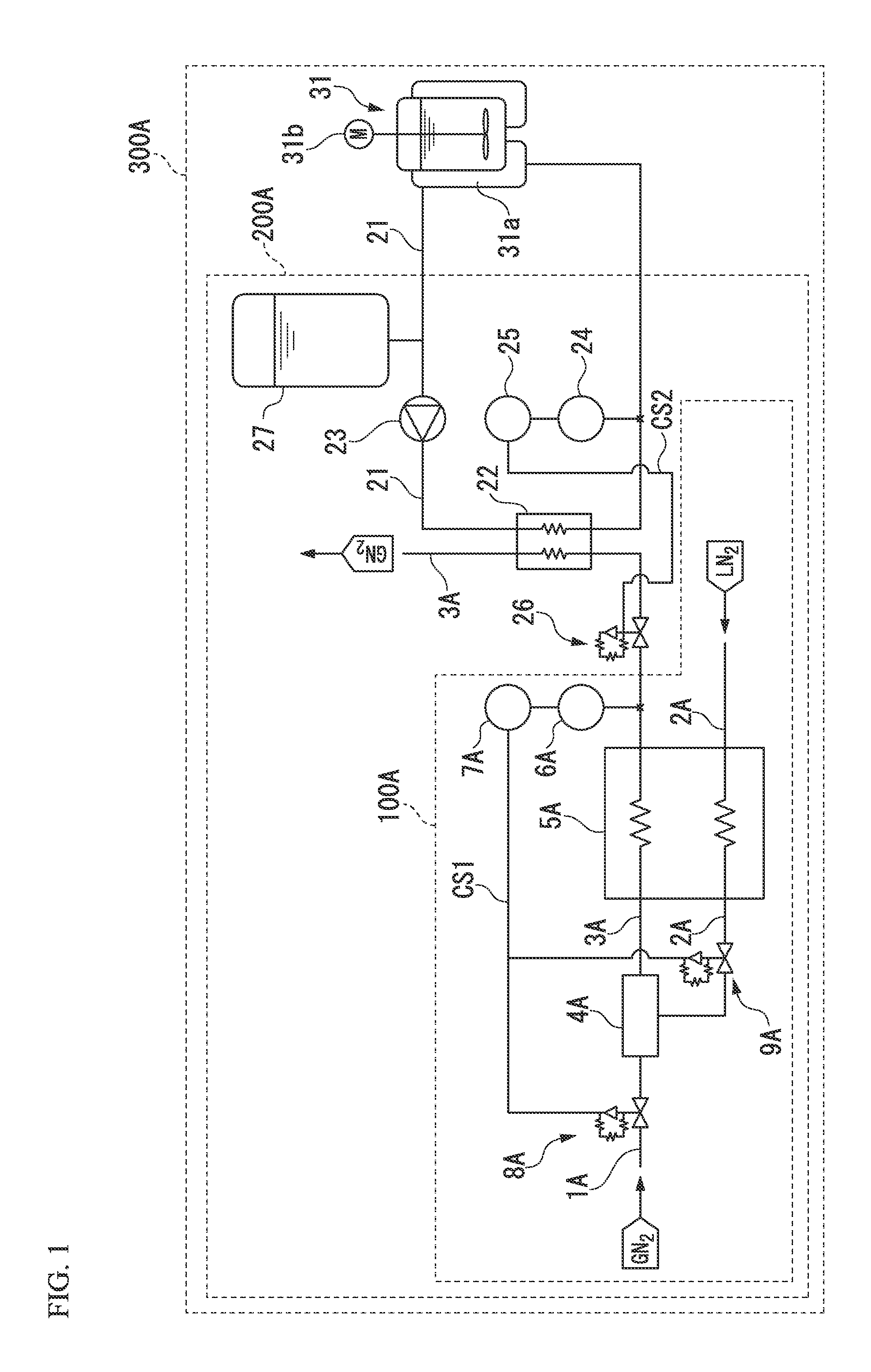
[0058]A low-temperature gas supply device 100A, heat transfer medium-cooling device 200A, and low-temperature reaction control device 300A according to the first embodiment of the present invention will be explained. FIG. 1 is a schematic diagram according to the first embodiment, in which a low-temperature gas supply device, a heat transfer medium-cooling device, and low-temperature reaction control of the present invention are used.

[0059]As shown in FIG. 1, a low-temperature gas supply device 100A according to the first embodiment of the present invention includes a room temperature route 1A, from an one end of which a room temperature nitrogen gas (GN2)NNG is introduced as a gas of higher temperature than a low-temperature-liquefied gas described below, a low-temperature route 2A, from an one end of which a liquefied nitrogen (LN2)LN (for example, −196° C.) is introduced as the low-temperature-liquefied gas, a mixing route 3A, in which a mixed gas and a low-temperature nitrogen g...

second embodiment

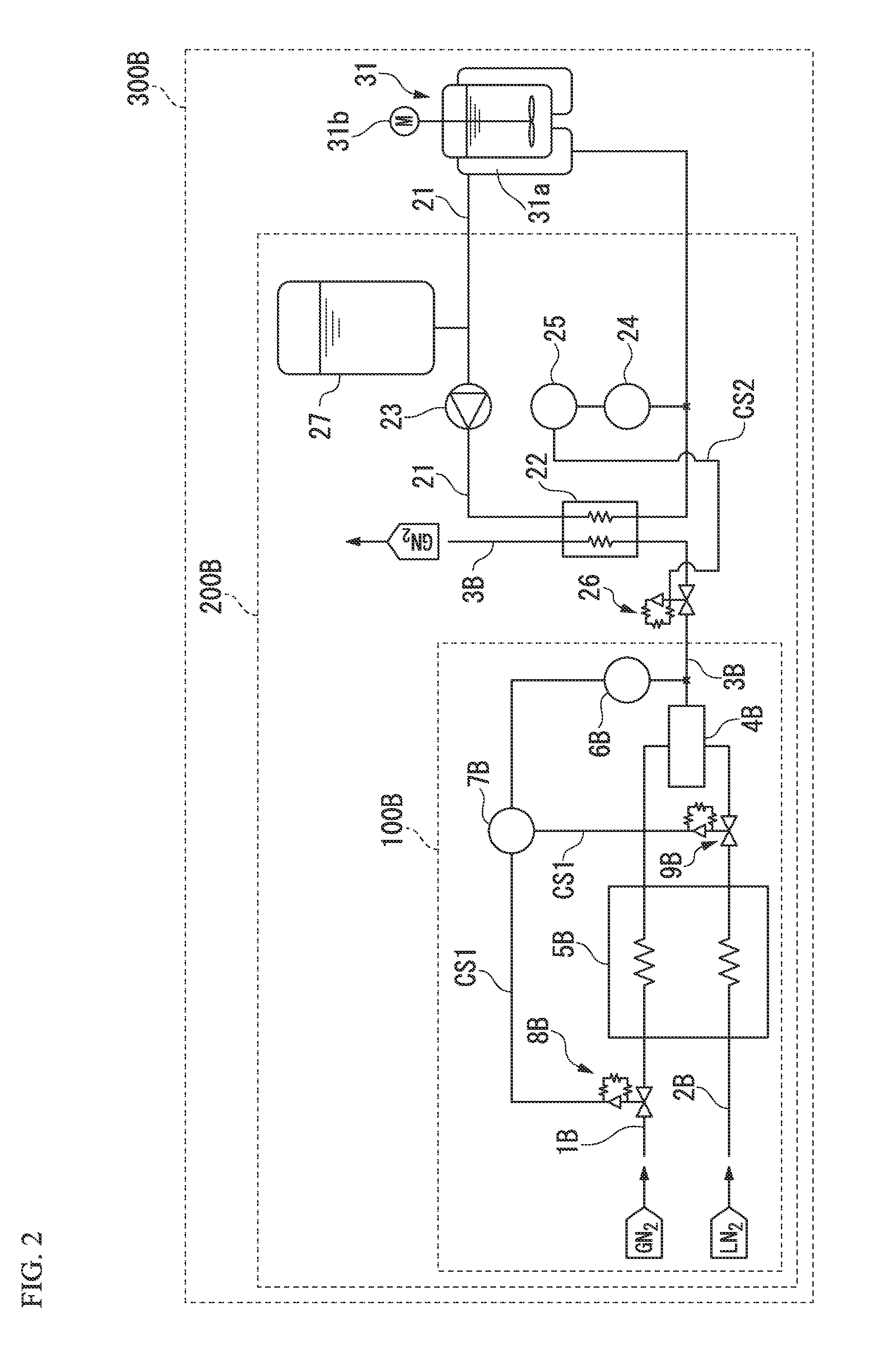
[0073]Next, the second embodiment according to the present invention will be explained. FIG. 2 shows a schematic diagram according to the second embodiment including the low-temperature gas supply device, the heat transfer medium-cooling device, the low-temperature reaction control device of the present invention.

[0074]As shown in FIG. 2, a low-temperature gas supply device 100B according to the second embodiment of the present invention includes a room temperature route 1B, from an one end of which a room temperature nitrogen gas (GN2)NNG is introduced, a low-temperature route 2B, from an one end of which a liquefied nitrogen (LN2)LN (for example, −196° C.) is introduced, a mixing route 3B, in which a low-temperature nitrogen gas refrigerant described below flows, a first heat exchanger 5B, in which the room temperature nitrogen gas NNG introduced from the room temperature route 113 and the liquefied nitrogen LN introduced from the low-temperature route 2B are heat-exchanged with e...

third embodiment

[0088]Next, the third embodiment according to the present invention will be explained. FIG. 3 shows a schematic diagram according to the third embodiment including the low-temperature gas supply device, the heat transfer medium-cooling device, and the low-temperature reaction control device of the present invention.

[0089]As shown in FIG. 3, a low-temperature gas supply device 100C according to the third embodiment of the present invention includes a room temperature route 1C, from an one end of which a room temperature nitrogen gas (GN2)NNG is introduced as a gas of higher temperature than a low-temperature-liquefied gas described below, a low-temperature route 2C, from one end of which a liquefied nitrogen (LN2)LN (for example, −196° C.) is introduced as the low-temperature-liquefied gas, a mixing route 3C, in which a mixed gas and a low-temperature nitrogen gas refrigerant described below flows, an ejector (mixed device) 4C, in which the room temperature nitrogen gas NNG introduce...


PUM

PropertyMeasurementUnit
Temperatureaaaaaaaaaa

Abstract

A low-temperature gas supply device is provided with a first heat exchanger, in which a mixed gas mixing a vaporization gas of a low-temperature-liquefied gas with a gas of a temperature higher than the low-temperature-liquefied gas and the low-temperature-liquefied gas are introduced and heat-exchanged with each other, and the mixed gas is discharged as a low-temperature gas refrigerant and the low-temperature-liquefied gas is discharged as the vaporization gas; a mixing unit, in which the gas and the vaporization gas discharged from the first heat exchanger are mixed and discharged as the mixed gas; and a first control unit, in which, based on the difference between a detected temperature of the low-temperature gas refrigerant and an intended temperature, respective amounts of the gas introduced to the mixing unit and the vaporization gas are adjusted to control the temperature of the low-temperature gas refrigerant to the intended temperature.

Description

TECHNICAL FIELD[0001]The present invention relates to a low-temperature gas supply device, heat transfer medium-cooling device, and low-temperature reaction control device. The present application claims priority on the basis of Japanese Patent Application No. 2011-223716, filed in Japan on Oct. 11, 2011, the contents of which are incorporated herein by reference.BACKGROUND ART[0002]In a chemical process such as an organic synthesis and crystallization, a highly accurate control of temperature is required in the low-temperature range. Therefore, as shown in the patent documents described below, a low-temperature reaction device may be used. In the low-temperature reaction device, a double structure container disposed with an independent vessel (jacket), in which a heat transfer medium is able to flow outside a reaction vessel, is used, and by supplying a heat transfer medium controlled to a low temperature to the jacket part, the reaction liquid in the reaction vessel is cooled and ...

Claims


Application Information

Patent Timeline
IPC IPC(8): F25J5/00F25J1/00B01F23/10
CPCF25J5/00F25J5/002F25J1/00F25D3/10
Inventor YAMAZUMI, SHIGEMASAYONEKURA, MASAHIROTAKEUCHI, MASAHIRO
Owner TAIYO NIPPON SANSO CORP
Learn More