Film and layered body

Active Publication Date: 2021-09-09
TORAY IND INC
View PDF0 Cites 0 Cited by
  • Summary
  • Abstract
  • Description
  • Claims
  • Application Information

AI Technical Summary

Benefits of technology

The present invention provides a film that can be easily applied to curved surfaces, while maintaining a high level of reflectance and transmittance. The film has a layer constitution that expands the range of reflections, while also being flexible and easy to conform to the shape of the surface. This solves the problem of requiring a larger number of layers and higher equipment cost to achieve an intended reflectance.

Problems solved by technology

In the case of the method that uses a heat absorbing agent described in Patent document 1, solar light coming from the outside is converted into thermal energy, and accordingly, there is a disadvantage that the heat may be radiated into the room to cause a decrease in the heat shield efficiency.
In addition, the absorption of heat may cause an increase in the glass temperature, possibly leading to damage to the glass plate due to the difference from the outside air temperature.
In the case of the method that uses a metal film formed on the surface of glass by sputtering described in Patent document 2, not only heat but also electromagnetic waves are shielded, possibly making communications devices unable to work appropriately in automobiles, buildings, or the like.
In this case, such a film has the disadvantage of being unable to work appropriately in such members as automobile windshield that need high transparency.

Method used


Image

  • Film and layered body
  • Film and layered body
  • Film and layered body

Examples


example 1

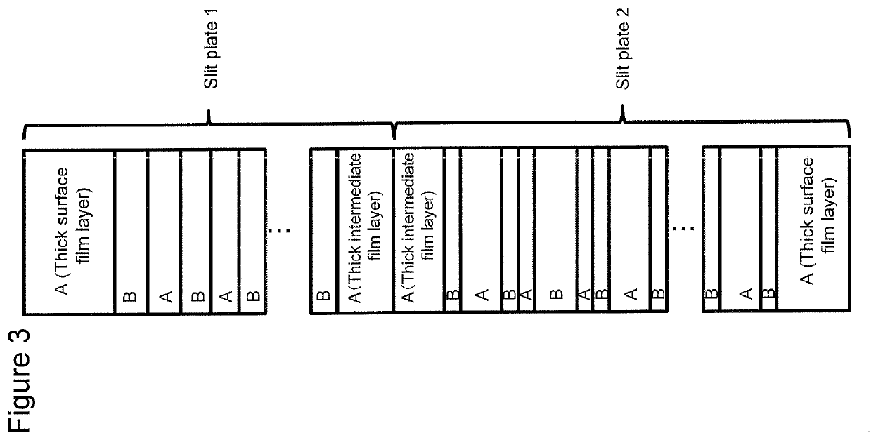
[0137]A PEN polymer with an intrinsic viscosity of 0.60 and a Tm of 268° C. was used as thermoplastic resin C whereas a mixture of a copolymer of a PET resin with 30 mol % cyclohexanedimethanol and a polyethylene terephthalate polymer (manufactured by Toray Industries, Inc.; IV 0.65, Tg 79° C., Tm 255° C.) mixed at a mass ratio of 82:18 was used as thermoplastic resin D (shown as PETG resin in Tables), and the lamination apparatus was replaced with lamination apparatus 2. Except for these, the same procedure as in Comparative example 1 was carried out. Lamination apparatus 2 was designed for only a thick layer of 7 μm, a thick intermediate layer of 3 μm, both located at each surface, and lamination unit 2 containing 654 layers and configured to produce a laminated film having a total of 657 stacked layers in the following layer constitution: (thick surface layer of thermoplastic resin C) / (lamination unit 2 containing a total of 327 C-layers and D-layers stacked alternately in the th...

example 2

[0141]Except for using lamination apparatus 3, the same procedure as in Example 1 was carried out. Lamination apparatus 3 had a layer thickness constitution designed for forming a 5 μm layer as a thick surface layer and lamination unit 1 of 149 layers, subsequently forming a thick intermediate layer of 5 μm and lamination unit 2 of 297 layers, and additionally forming a 5 μm layer as the thick surface layer on the lamination unit 2 side to produce a laminated film (total thickness of 60 μm) containing a total of 449 stacked layers in the following layer constitution: (thick surface layer of thermoplastic resin A) / (lamination unit 1 containing a total of 149 A-layers and B-layers stacked alternately in the thickness direction) / (thick intermediate layer of thermoplastic resin A) / (lamination unit 2 containing a total of 297 C-layers and D-layers stacked alternately in the thickness direction) / (thick surface layer of thermoplastic resin A). The total thickness (d1) of lamination unit 1 ...

example 3

[0143]Except for using lamination apparatus 4, the same procedure as in Example 2 was carried out. Lamination apparatus 4 had a layer thickness constitution designed for forming a 6 μm layer as a thick surface layer and lamination unit 1 of 149 layers, subsequently forming a thick intermediate layer of 5 μm and lamination unit 2 of 357 layers, and additionally forming a 4 μm layer as the thick surface layer on the lamination unit 2 side to produce a laminated film (total thickness of 63 μm) containing a total of 599 stacked layers in the following layer constitution: (thick surface layer of thermoplastic resin A) / (lamination unit 1 containing a total of 149 A-layers and B-layers stacked alternately in the thickness direction) / (thick intermediate layer of thermoplastic resin A) / (lamination unit 2 containing a total of 357 C-layers and D-layers stacked alternately in the thickness direction) / (thick surface layer of thermoplastic resin A). The total thickness (d1) of lamination unit 1 ...


PUM

PropertyMeasurementUnit
Fractionaaaaaaaaaa
Fractionaaaaaaaaaa
Thicknessaaaaaaaaaa

Abstract

The present invention is a film having at least one reflection band in which the reflectance is 30% or greater continuously in at least a 100-nm range in a wavelength range of 1200-1800 nm when light is incident from at least one side, the mean transmittance in a wavelength range of 430-600 nm is 70% or greater, and the average value of the axial rigidity of the film in the principal orientation axis direction of the film and in the direction orthogonal thereto is 45 N / m or less.

Description

CROSS REFERENCE TO RELATED APPLICATIONS[0001]This is the U.S. National Phase application of PCT / JP2017 / 023202, filed Jun. 23, 2017, which claims priority to Japanese Patent Application No. 2016-139956, filed Jul. 15, 2016, Japanese Patent Application No. 2016-237298, filed Dec. 7, 2016, and Japanese Patent Application No. 2017-019243, filed Feb. 6, 2017, the disclosures of each of these applications being incorporated herein by reference in their entireties for all purposes.FIELD OF THE INVENTION[0002]The present invention relates to a film and a layered body.BACKGROUND OF THE INVENTION[0003]In recent years, attention has been drawn to the application of heat-shielding glass that can reduce the inflow of external heat in the summer, heat of sunlight in particular, to vehicles such as automobiles and electric trains, and window panes of buildings, under the regulation of emission of carbon dioxide for environmental protection.[0004]Techniques to produce such heat-shielding glass incl...

Claims


Application Information

Patent Timeline
IPC IPC(8): G02B5/26G02B5/28B32B27/08G02B1/14
CPCG02B5/26G02B1/14B32B27/08G02B5/282B32B27/00G02B5/0841G02B5/208G02B5/285G02B5/287
Inventor ARIKE, TAKAFUMIMASUDA, YOSHIHIROAOYAMA, SHIGERU
Owner TORAY IND INC
Why Eureka
Try Eureka