
Solar cell module and solar cell panel

Inactive Publication Date: 2016-02-18
DAI NIPPON PRINTING CO LTD
View PDF2 Cites 17 Cited by
  • Summary
  • Abstract
  • Description
  • Claims
  • Application Information

AI Technical Summary

Benefits of technology

The present invention relates to a solar cell module and panel that have a first colored layer between the adjacent solar cell elements and a diffusion layer on the light receiving surface. This first colored layer and diffusion layer provide a difference in luminance between the color of the region above the solar cell element and the color of the region above the gap between the adjacent solar cell elements being up to 2.3. This allows for a clear underlayer before the second colored layer is formed, providing a high-quality coloring function and designability. The second colored layer can be formed above the clear underlayer, even if there is no color unevenness, allowing for enhanced design options. Alternatively, the first colored layer can be formed between the adjacent solar cell modules to control color unevenness between them.

Problems solved by technology

However, such technical measures merely provide designability to the extent of whitening evenly the light receiving surface of the solar cell module or the solar cell panel, or making a gap between the adjacent solar cell elements less noticeable, or, lacing the light receiving surface of the solar cell module, thus leading to difficulty in providing the light receiving surface with a high grade designability such as a desired motif or characters.

Method used


Image

  • Solar cell module and solar cell panel
  • Solar cell module and solar cell panel
  • Solar cell module and solar cell panel

Examples


first embodiment

of the Present Invention

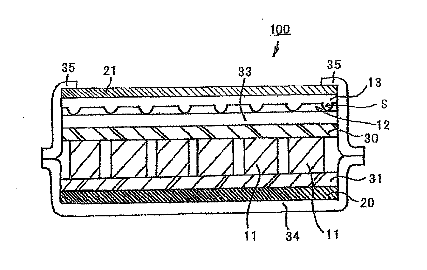
[0028]FIG. 1 is a schematic cross-sectional view of the solar cell module according to the first embodiment of the present invention.

[0029]The solar cell module 100 according to this embodiment includes two or more solar cell elements 11, 11 . . . placed at intervals; a light receiving surface side thermoplastic resin layer 30 and a back surface side thermoplastic resin layer 31 between which these solar cell elements 11, 11 . . . are held; a polyethylene terephthalate resin layer placed on the light receiving surface side thermoplastic resin layer 30; a back sheet 34 placed on the back surface of the solar cell module 100; and a sealing material 35 placed at the edge of the light receiving surface of the solar cell module 100, and a first colored layer 20 is provided between the back sheet 34 and the back surface side thermoplastic resin layer 31; and further a diffusion layer 13 is provided on the side of the light receiving surface. In this state, a differ...

second embodiment

of the Present Invention

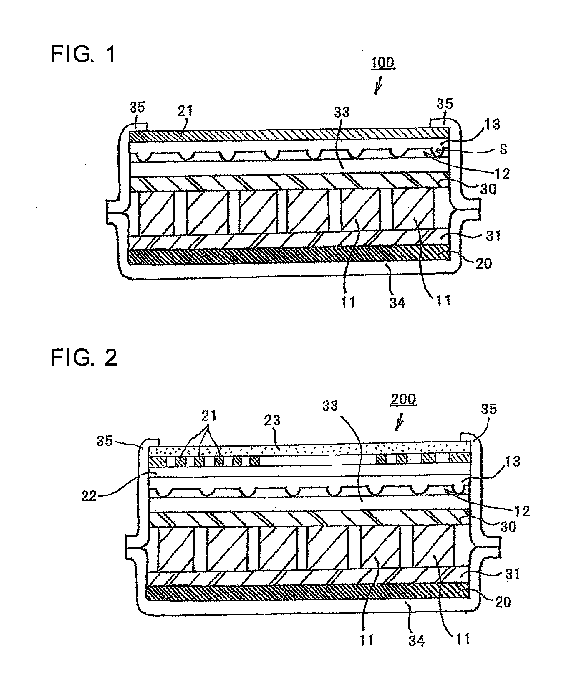
[0062]FIG. 2 is a schematic cross-sectional view of the solar cell module according to the second embodiment of the present invention.

[0063]In FIG. 2, the same structural components as those of the solar cell module 100 according to the first embodiment of the present invention as shown in FIG. 1 have the same reference numerals. The description of the same structural components as those of the solar cell module 100 according to the first embodiment of the present invention will be omitted.

(Second Colored Layer)

[0064]The solar cell module 200 according to this embodiment of the present invention has a feature that the second colored layer is formed not as the so-called solid layer, but as a partially patterned layer, and such a patterned layer is provided in the form of dots, as shown in FIG. 2.

[0065]Providing the second colored layer 21 in the form of dots makes it possible to increase an amount of incident light on the solar cell element 11, thus being pref...

third embodiment

of the Present Invention

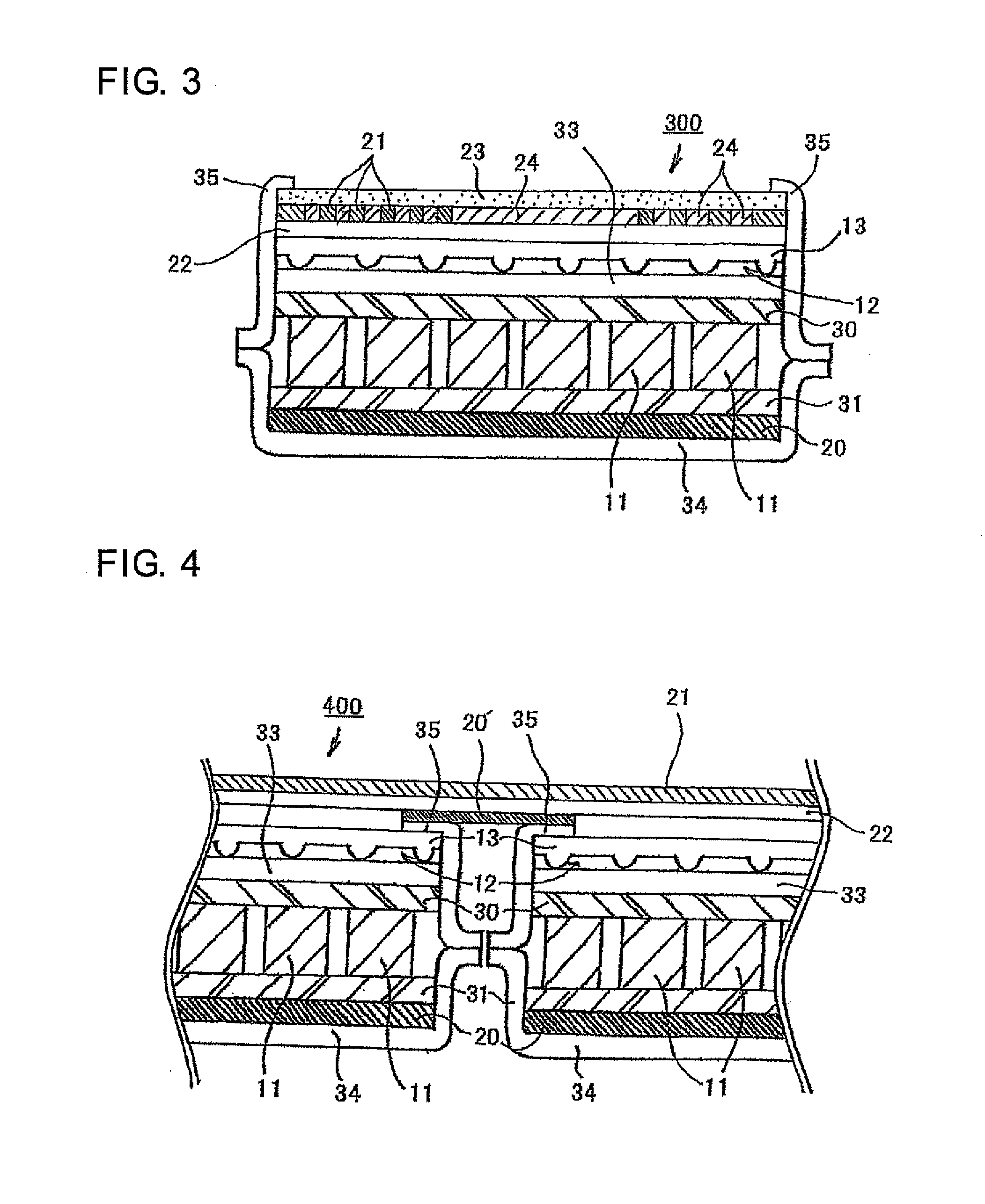
[0079]FIG. 3 is a schematic cross-sectional view of the solar cell module according to the third embodiment of the present invention.

[0080]In FIG. 3, the same structural components as those of the solar cell modules 100, 200 according to the first and second embodiments of the present invention as shown in FIG. 2 have the same reference numerals. The description of the same structural components as those of the solar cell modules 100, 200 according to the first and second embodiments of the present invention will be omitted.

(Second Transparent Layer)

[0081]The solar cell module 300 according to this embodiment of the present invention is characterized in that the second colored layer is composed of a plurality of colored sections 21, 21 formed on the same plane, so as to provide a patterned layer, and the second transparent layer is composed of a plurality of transparent sections 24 provided between the adjacent colored sections 21, 21 of the second colored la...


PUM


Abstract

A solar cell module comprises: two or more solar cell elements provided at intervals; a first colored layer provided between adjacent solar cell elements; and a diffusion layer and a second colored layer provided, on a side of a light receiving surface of the solar cell module, directly or through another layer in this order from the solar cell element side. A difference in luminance between a color of a region above the solar cell element and a color of a region above a gap between adjacent solar cell elements, in an anterior view of a surface of the diffusion layer of the solar cell module with the second colored layer removed, is up to 2.3.

Description

TECHNICAL FIELD[0001]The present invention relates to a solar cell module and a solar cell panel.BACKGROUND OF THE INVENTION[0002]There have currently been developed efforts to limit emission of CO2 on a worldwide scale, as a measure to prevent global warming. A solar cell module in which a plurality of solar cells are electrically connected to each other, and a solar cell panel in which a plurality of such solar cell modules are electrically connected to each other, have attracted public attention as a clean power-generating equipment, and research and development regarding them have been carried out.[0003]In addition, the solar cell modules or the solar cell panels have recently been mounted not only on various kinds of outdoor articles, but also on various kinds of and articles for utilization of them. However, they have sometimes caused a problem of designability. Therefore, there is a demand to provide the whole light receiving surface of the solar cell modules or the solar cel...

Claims


Application Information

Patent Timeline
IPC IPC(8): H02S99/00H01L31/042
CPCH01L31/042H02S99/00H01G9/2068H01L31/02H01L31/048H02S40/20Y02E10/542Y02E10/50
Inventor SASAKI, MIHO
Owner DAI NIPPON PRINTING CO LTD
Learn More