Power array with staggered arrangement for improving on-resistance and safe operating area

a power array and staggered arrangement technology, applied in the field of power arrays, can solve the problems of low on-resistance and reliability of the device, and achieve the effects of suppressing heat accumulation in the device, widening the safe operating area, and low on-resistan

Active Publication Date: 2014-12-18
UNITED MICROELECTRONICS CORP
View PDF3 Cites 3 Cited by
  • Summary
  • Abstract
  • Description
  • Claims
  • Application Information

AI Technical Summary

Benefits of technology

[0008]To obtain low on-resistance (RDSon) and a widen safe operating area (SOA), a power array with a novel and staggered arrangement is provided in the present invention. The staggered arrangement of device units in the present invention may gain a larger distance between adjacent drain regions, thereby suppressing the heat accumulation in the device, especially in the drain region. The burn-out voltage and the safe operating area are accordingly increased.

Problems solved by technology

Especially in the case of bigger array devices, thermal problem always impact the reliability of the device, so a widen SOA may ensure that no burn-out issue occur in the active area.
How to improve the breakdown voltage while maintaining a low on-resistance becomes a challenge.

Method used


Image

  • Power array with staggered arrangement for improving on-resistance and safe operating area
  • Power array with staggered arrangement for improving on-resistance and safe operating area
  • Power array with staggered arrangement for improving on-resistance and safe operating area

Examples


Embodiment Construction

[0016]In the following detailed description of the invention, reference is made to the accompanying drawings which form a part hereof, and in which is shown, by way of illustration, specific embodiments in which the invention may be practiced. These embodiments are described in sufficient detail to enable those skilled in the art to practice the invention. Other embodiments may be utilized and structural, logical, and electrical changes may be made without departing from the scope of the present invention.

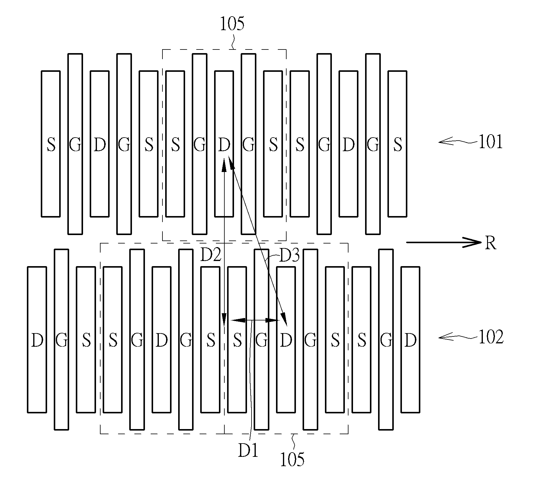
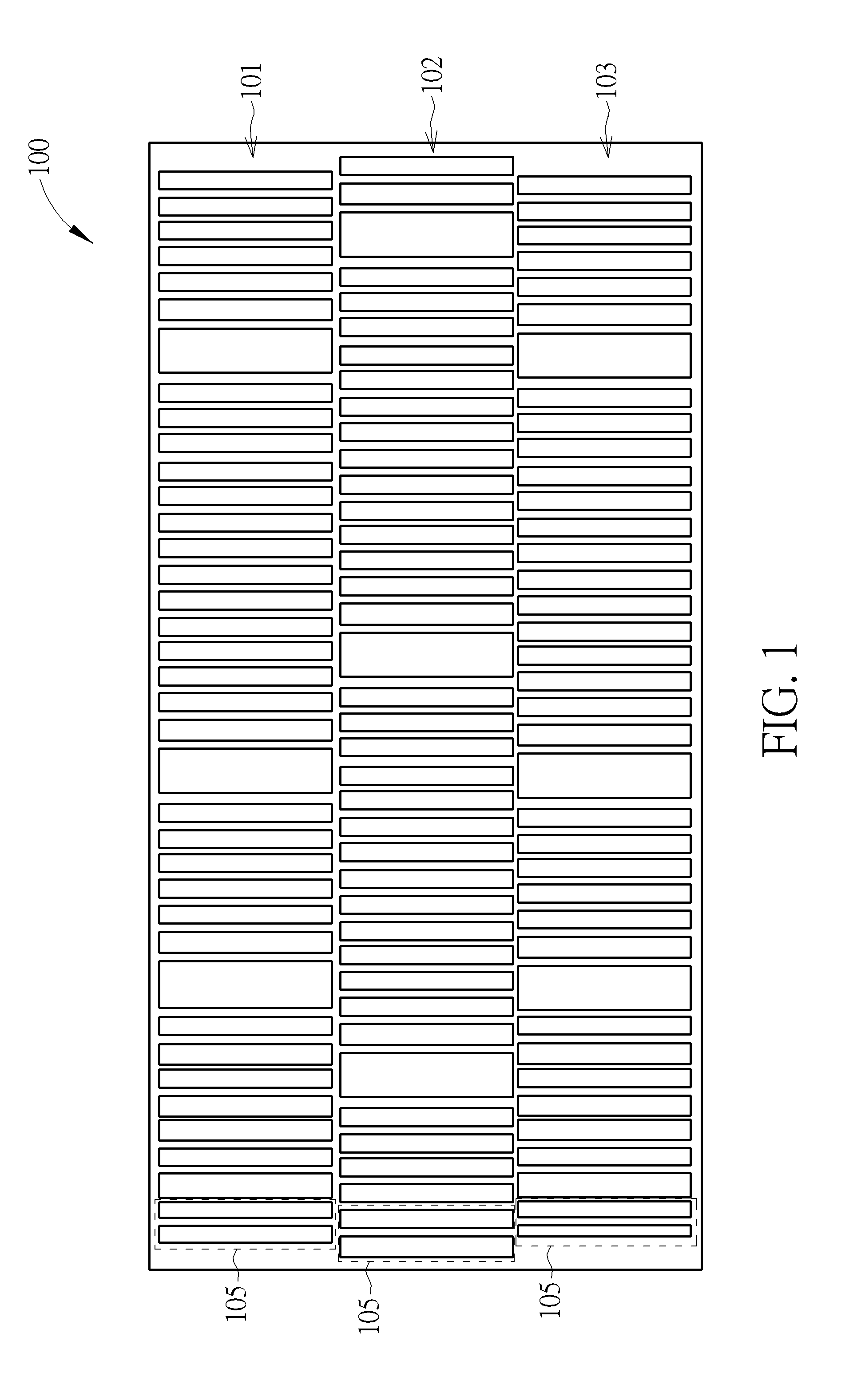
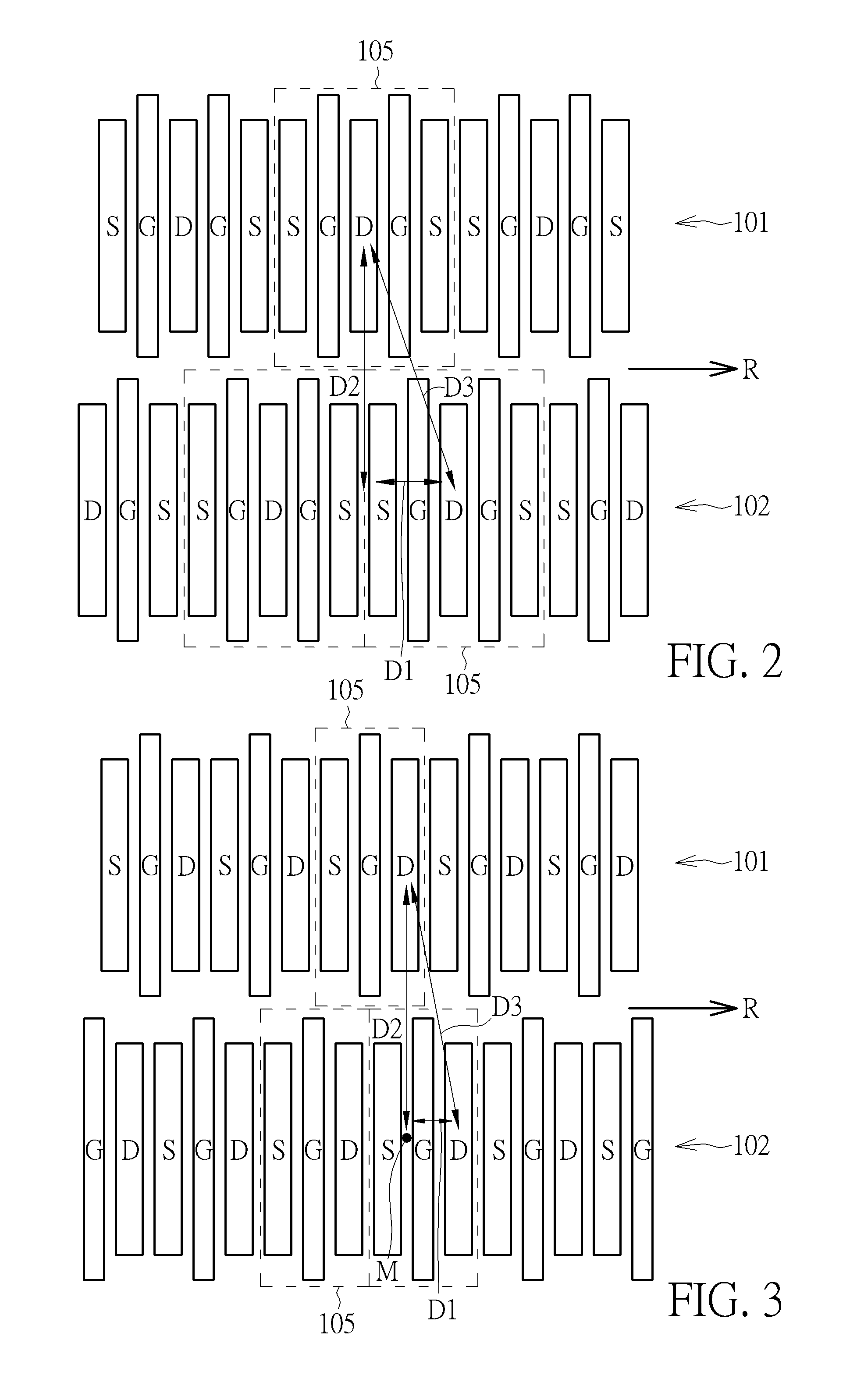
[0017]The embodiments will now be explained with reference to the accompanying drawings to provide a better understanding to the structure of the present invention. First, as shown in FIG. 1, a power array 100 is provided with at least two device rows in a staggered arrangement (in this embodiment, three device rows 101 / 102 / 103 are shown in FIG. 1). Each device row further includes a plurality of parallel device units 105, such as LDMOS, FDMOS, CMOS or DEMOS, arranged along the dev...


PUM


Abstract

A power array with a staggered arrangement for improving on-resistance and safe operating area of a device is provided. Each power array includes two or more rows with a plurality of parallel device units arranged along the row. Each device unit includes a source region, a drain region, and a gate disposed between the source region and the drain region, wherein each drain region is offset from the adjacent drain region of adjacent rows in a row direction.

Description

BACKGROUND OF THE INVENTION[0001]1. Field of the Invention[0002]The present invention relates generally to a power array, and more particularly, to a power array with a staggered arrangement for improving on-resistance (RDSon) and safe operating area (SOA).[0003]2. Description of the Prior Art[0004]Following the semiconductor industry development with time, high voltage devices have been widely applied in many electronic systems. These high voltage devices with various voltage levels are implemented as LDMOS, CMOS or DEMOS devices included in integrated circuits (IC). For example, low, intermediate and high power devices maybe provided in ICs. Low power devices maybe used in complementary metal oxide semiconductor (CMOS) for logic circuitry, intermediate voltage devices for analog circuitry and high power devices for high voltage output interfaces. It is desirable for high voltage devices to have a fast switching speed. The performances of such devices depend on, for example, the on...

Claims


Application Information

Patent Timeline
Patent Type & Authority Applications(United States)
IPC IPC(8): H01L27/088H01L27/092
CPCH01L27/092H01L27/088H01L29/7816H01L27/0207H01L29/0692H01L29/0696H01L29/4238H01L29/78
Inventor CHEN, WEI-LINLIN, KE-FENGLEE, CHIU-LINGLEE, CHIU-TEWANG, CHIH-CHUNGLIAO, HSUAN-PO
Owner UNITED MICROELECTRONICS CORP
Why Eureka
Try Eureka