
Unit and method for cooling, and apparatus and method for treating substrate

a technology of cooling and substrate, applied in lighting and heating apparatus, ventilation systems, heating types, etc., can solve the problems of reducing process treatment rate, cooling rate may decrease, and substrate thermal stress and generating particles, so as to achieve quick uniform cooling of substra

Active Publication Date: 2014-12-25
PSK INC
View PDF5 Cites 8 Cited by
  • Summary
  • Abstract
  • Description
  • Claims
  • Application Information

AI Technical Summary

Benefits of technology

The present invention is a substrate treating apparatus that can quickly and evenly cool a substrate, and also reduce the production of particles.

Problems solved by technology

The conduction method may cause thermal stress on the substrate and generate particles.
However, according to the convection method, a cooling rate may decrease to reduce a process treating rate.

Method used


Image

  • Unit and method for cooling, and apparatus and method for treating substrate
  • Unit and method for cooling, and apparatus and method for treating substrate
  • Unit and method for cooling, and apparatus and method for treating substrate

Examples


Embodiment Construction

[0059]Preferred embodiments of the present invention will be described below in more detail with reference to the accompanying drawings. The present invention may, however, be embodied in different forms and should not be constructed as limited to the embodiments set forth herein. Rather, these embodiments are provided so that this disclosure will be thorough and complete, and will fully convey the scope of the present invention to those skilled in the art. In the drawings, the thicknesses of layers and regions are exaggerated for clarity.

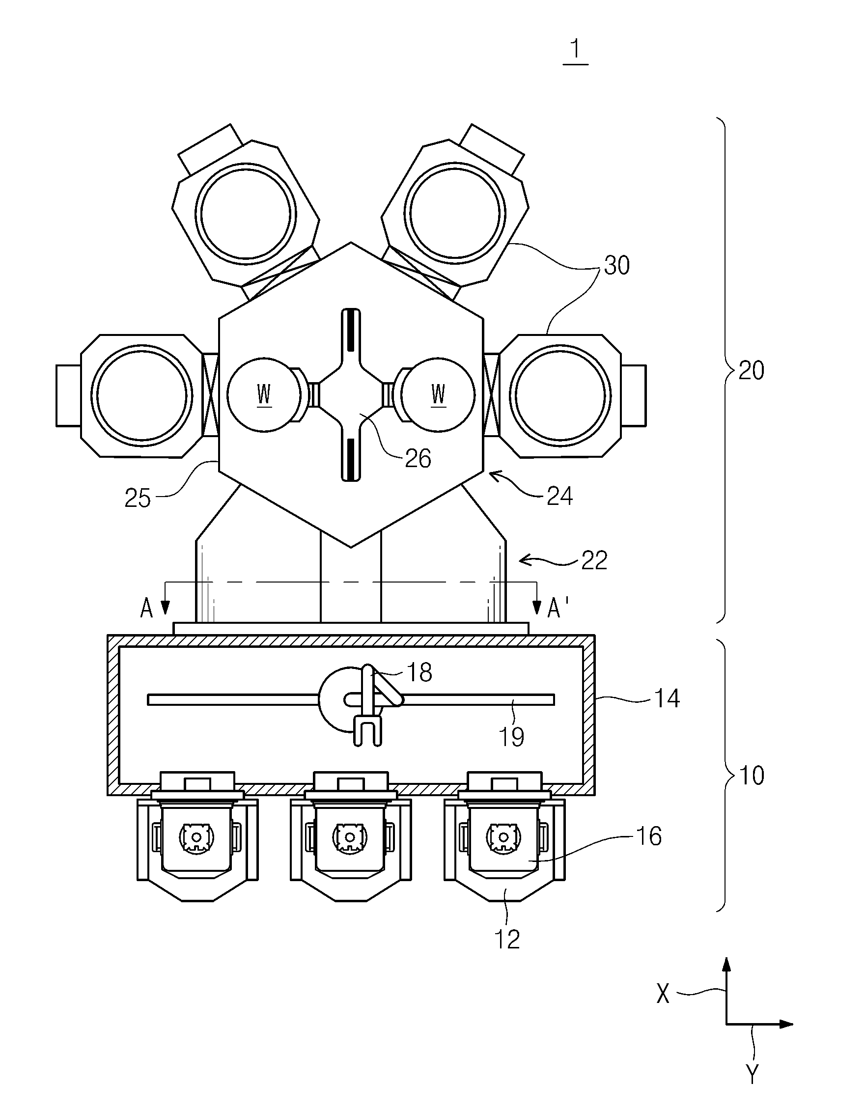
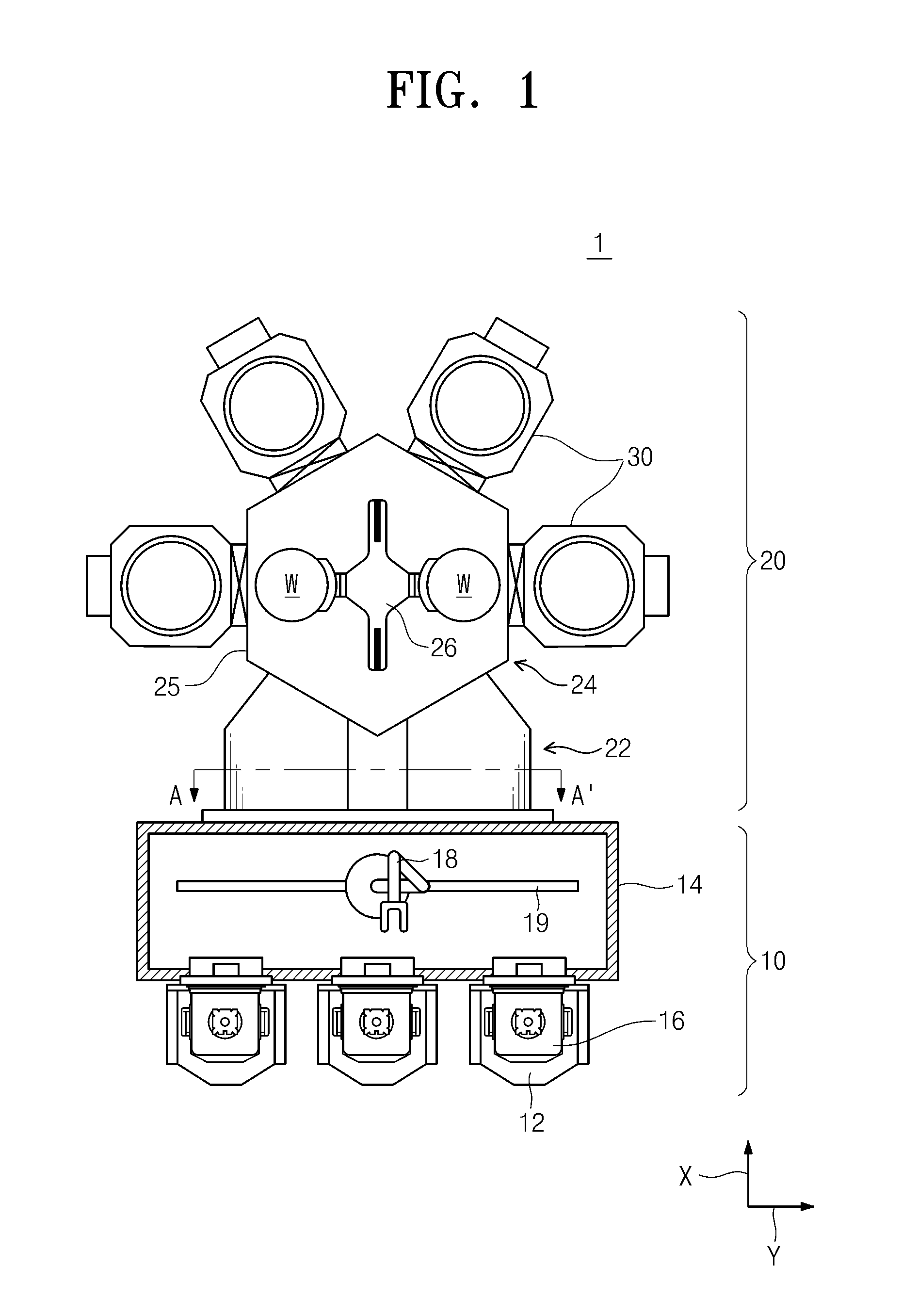
[0060]FIG. 1 is a schematic plan view of a substrate treating equipment according to an embodiment of the present invention.

[0061]Referring to FIG. 1, a substrate treating apparatus 1 includes an equipment front end module (EFEM) 10 and a process treating chamber 20. The EFEM 10 and the process treating chamber 20 may be arranged in one direction. Hereinafter, the direction in which the EFEM 10 and the process treating chamber 20 are arranged may b...


PUM


Abstract

Provided is a substrate treating apparatus. The substrate treating apparatus includes an equipment front end module, a loadlock chamber, a transfer chamber, and a plurality of process chambers. The loadlock chamber includes a cooling unit for cooling a substrate treated in the process chambers, and the cooling unit includes a cooling chamber having an inner space, the cooling chamber having a gas inflow hole in one surface thereof, wherein support pins on which the substrate is placed are disposed around a circumference of the gas injection hole, a cooling gas injection part supplying a cooling gas toward the gas inflow hole, and a gas exhaust part exhausting the cooling gas supplied into the cooling chamber and fumes generated from the substrate to the outside of the cooling chamber.

Description

CROSS-REFERENCE TO RELATED APPLICATIONS[0001]This U.S. non-provisional patent application claims priority under 35 U.S.C. §119 of Korean Patent Application No. 10-2013-0071061, filed on Jun. 20, 2013, the entire contents of which are hereby incorporated by reference.BACKGROUND OF THE INVENTION[0002]In general, semiconductors are manufactured by successively performing a series of unit processes such as layer formation, pattern formation, metal interconnection formation, and the like. Semiconductor manufacturing equipment may include a loadport, an equipment front end module (EFEM), a loadlock chamber, a transfer chamber, and a process chamber. The loadport supports a carrier in which a substrate is accommodated, and the EFEM includes a transfer robot for transferring the substrate between the loadport and the chambers. A treated substrate before being transferred into the loadport or a substrate to be treated before being transferred into the process chamber may stand by in the load...

Claims


Application Information

Patent Timeline
Patent Type & Authority Applications(United States)
IPC IPC(8): H01L21/67F24F9/00F24F7/00
CPCH01L21/67011F24F9/00F24F7/00H01L21/67109H01L21/67201
Inventor YANG, SEUNG-KOOKLEE, SEONG-WOOKSON, DAE-HEE
Owner PSK INC
Learn More