Blood Components Separation Device, and Centrifugal Separator

a separation device and centrifugal separator technology, applied in the direction of centrifuges, engine seals, other medical devices, etc., can solve the problems of abnormal noise generation, achieve the effect of suppressing high-pitched noise, preventing the generation of high-pitched noise, and suppressing high-pitched nois

Inactive Publication Date: 2014-12-25
TERUMO KK
View PDF1 Cites 4 Cited by
  • Summary
  • Abstract
  • Description
  • Claims
  • Application Information

AI Technical Summary

Benefits of technology

[0014]Since the blood component separation device according to the present invention is structured as described above, the blood component separation device provides operation and effect to be described below.
[0015]The inventor of the present invention attempted various measures to prevent generation of high-pitched noise by changing roughness of the rotating and sliding portion between the stator and the rotor, for example. However, high-pitched noise generation couldn't be suppressed to none. Finally, the inventor found that high-pitched noise generation could be suppressed by setting the rubber hardness of the ring cap to between 60 and 66 inclusive. The reason will be described below.
[0016]According to the structure described in (1) above, stick-slip phenomenon on the sliding surface generated by the rotor with respect to the stator can be suppressed, and thus high-pitched noise generation can be suppressed.
[0017]Conventionally, the rotating and sliding portion has been pressed by high pressing force in order to enhance sealing performance. The inventor of the present invention has found that stick-slip is therefore generated and high-pitched noise is generated upon slipping. The inventor has therefore considered that high-pitched noise generation can be suppressed if stick-slip phenomenon can be suppressed and confirmed the fact by an experiment.
[0018]In addition, the inventor of the present invention has found that that pressing force at the rotating and sliding portion between the stator and the rotor can be 500 grams or less by setting the rubber hardness to 66 or less by the structure described in (2) above.
[0019]More specifically, in the conventional blood component separation device, the rotor and the stator of the centrifugal separator has been pressed for a predetermined distance when the centrifugal separator is fitted. Because of this, the predetermined pressing force becomes 500 grams or more when the rubber hardness of the ring cap is 66 or more and thus elastic deformation of the ring cap is small. Thus, stick-slip is generated. In addition, since the rubber hardness of 60 or less degrades sealing performance, the rubber hardness is set to 60 or more.

Problems solved by technology

At this time, a ring on rotor side and a ring on stator side are in contact with and slide on each other, so that abnormal noise is generated.

Method used


Image

  • Blood Components Separation Device, and Centrifugal Separator
  • Blood Components Separation Device, and Centrifugal Separator
  • Blood Components Separation Device, and Centrifugal Separator

Examples


Embodiment Construction

[0039]First, an embodiment of the present invention will be described with reference to accompanying drawings.

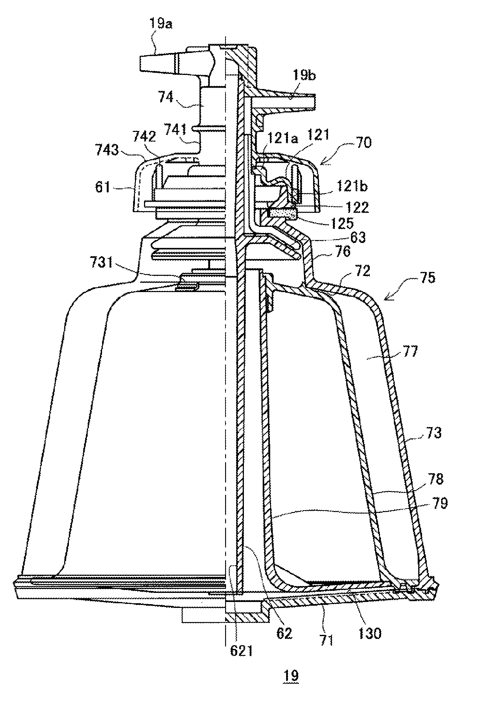
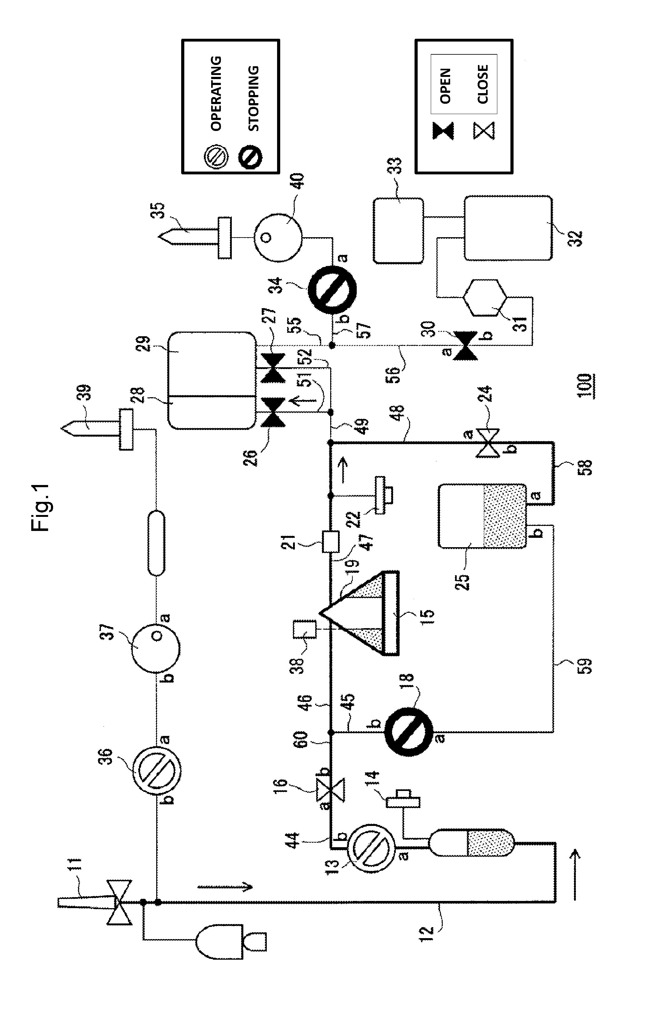
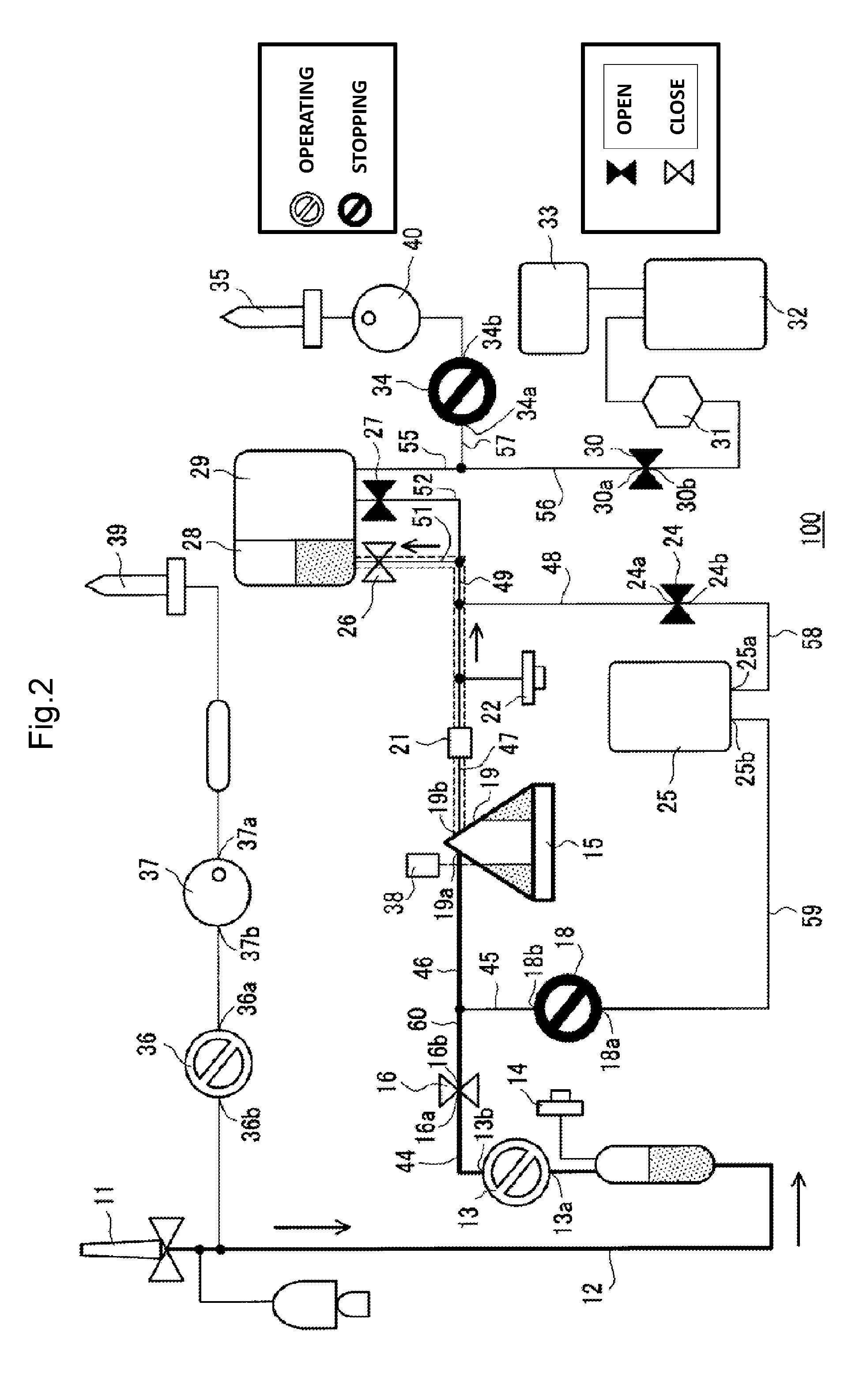
[0040]FIG. 1 illustrates a system configuration of a blood component separation device 100 according to the embodiment. FIG. 16 illustrates a configuration of the blood component separation device. The blood component separation device 100 according to the embodiment includes a blood component separation circuit 1 as illustrated in FIG. 16. The blood component separation circuit 1 includes a collection needle 11, an initial flow blood collection circuit 80 for collecting initial flow blood, a rotor having a blood storage space therein, a centrifugal bowl driving device 15 that rotatably drives the rotor, and an inlet 19a and an outlet 19b. The initial flow blood collection circuit 80 includes an initial flow blood collection bag 82, a sampling port 85, and an initial flow blood collection line 88. The blood component separation device 100 also includes a centrifugal bowl 19 ...


PUM


Abstract

For providing a blood separation device with which high-pitched noise is not generated even when a centrifugal separator is rotated before blood is introduced. A blood component separation device (100) includes a centrifugal bowl (19) including a stator (70) provided with an inlet (19a) and an outlet (19b) of blood or blood component and a rotor (75) provided rotatably with respect to the stator (70), a rotating and sliding portion between the stator (70) and the rotor (75) is sealed by pressing with predetermined pressing force, and the predetermined pressing force is 500 grams or less.

Description

TECHNICAL FIELD [0001]This invention relates to a blood component separation device having a centrifugal separator including a stator provided with an inlet and an outlet of blood or a blood component and a rotor provided rotatably with respect to the stator, and to a centrifugal separator used in the device.BACKGROUND ART [0002]Conventionally, blood collection is performed by two blood collection methods: whole blood collection and blood component collection. The blood component collection is separated to plasma collection and platelet collection. When platelet is necessary for treatment, a method for collecting platelet only and returning the other components to a blood donor is preferable. In order to take out platelet from blood, a blood component separation device provided with a centrifugal separator is used.[0003]A centrifugal separator described in Patent Literature 1 includes a stator provided with an inlet and an outlet of blood or a blood component and a rotor provided ro...

Claims


Application Information

Patent Timeline
Patent Type & Authority Applications(United States)
IPC IPC(8): B04B7/08
CPCB04B7/08A61M1/0209A61M1/3693B04B5/0442A61M2202/0427B04B2005/0464A61M1/3696A61M1/0218A61M1/0231F16J15/3476A61M2205/331A61M2205/42F16J15/344F16J15/36
Inventor IGARASHI, MASATSUGU
Owner TERUMO KK
Why Eureka
Try Eureka