Method and apparatus for recycling water

a technology of water recycling and water treatment, applied in the nature of treatment water, water treatment multi-stage treatment, borehole/well accessories, etc., can solve the problems of high specific energy consumption required for the mvc process, unfit for recycling of blowdown stream, and high operating cost associated with this amount of vapor compression, so as to reduce or eliminate the mvc power consumption, reduce the overall cost and footprint, and improve the overall economics of oil recovery

Active Publication Date: 2015-01-01
AQUATECH INT LLC
View PDF8 Cites 10 Cited by
  • Summary
  • Abstract
  • Description
  • Claims
  • Application Information

AI Technical Summary

Benefits of technology

[0008]We provide a once-through flash evaporation technology. In our technology, the above disadvantages are overcome by substantially reducing or eliminating the MVC power consumption and reducing the overall cost and footprint by eliminating the need for upstream cooling before the evaporator. This is a significant benefit to the thermal EOR project and improves the overall economics of oil recovery both on a capital cost basis as well as on an operating cost basis.

Problems solved by technology

In such processes, the blowdown stream is often unfit for recycle due to elevated content of dissolved solids that have been concentrated between 2× and 10× in the steam generator.
One disadvantage of the conventional method described above is the high specific energy consumption required for the MVC process.
The operating costs associated with this amount of vapor compression are high and represent a prohibitive barrier to using such a process for water recovery.
Another disadvantage of existing technology is that downstream evaporative zero liquid discharge (ZLD) technology typically also requires MVC design to complete the recovery / recycle of the OTSG blowdown stream.
An MVC process for the ZLD evaporator represents an additional parasitic power consumption on the overall process and is a drawback to the process that could otherwise be used for complete water recycle and zero liquid discharge.
A further disadvantage to the conventional process is that the system requires a cooling system to reduce the temperature of the OTSG blowdown stream to near-boiling temperature (typically 90-98° C.) prior to being fed to the evaporator system.
The requirement of the extra heat exchanger(s) adds cost and additional space or footprint is also consumed.

Method used


Image

  • Method and apparatus for recycling water
  • Method and apparatus for recycling water
  • Method and apparatus for recycling water

Examples


example # 2

EXAMPLE #2

[0072]In another embodiment the evaporation system includes a 1) flash drum; 2) thermocompressor; 3) primary evaporator; and 4) vapor condenser. (Refer to FIG. 6.)

[0073]In this embodiment the OTSG blowdown stream is accepted to the evaporator system without substantial upstream cooling. The OTSG blowdown is fed to the evaporator system existing at a high specific enthalpy, having a temperature and pressure equal to (or less than) that of the injection steam. Before being fed to the evaporator vessel itself, this high enthalpy stream can be flashed to a medium pressure to generate a vapor phase and a liquid phase.

[0074]The vapor phase, existing at a medium pressure, can be used as motive steam in a thermocompressor. The thermocompressor will use this high energy motive stream to load vapor being generated by the evaporator to produce a discharge water vapor stream that is suitable to drive evaporation and eliminate the need for a mechanical vapor compression.

[0075]Assume th...

example # 3

EXAMPLE #3

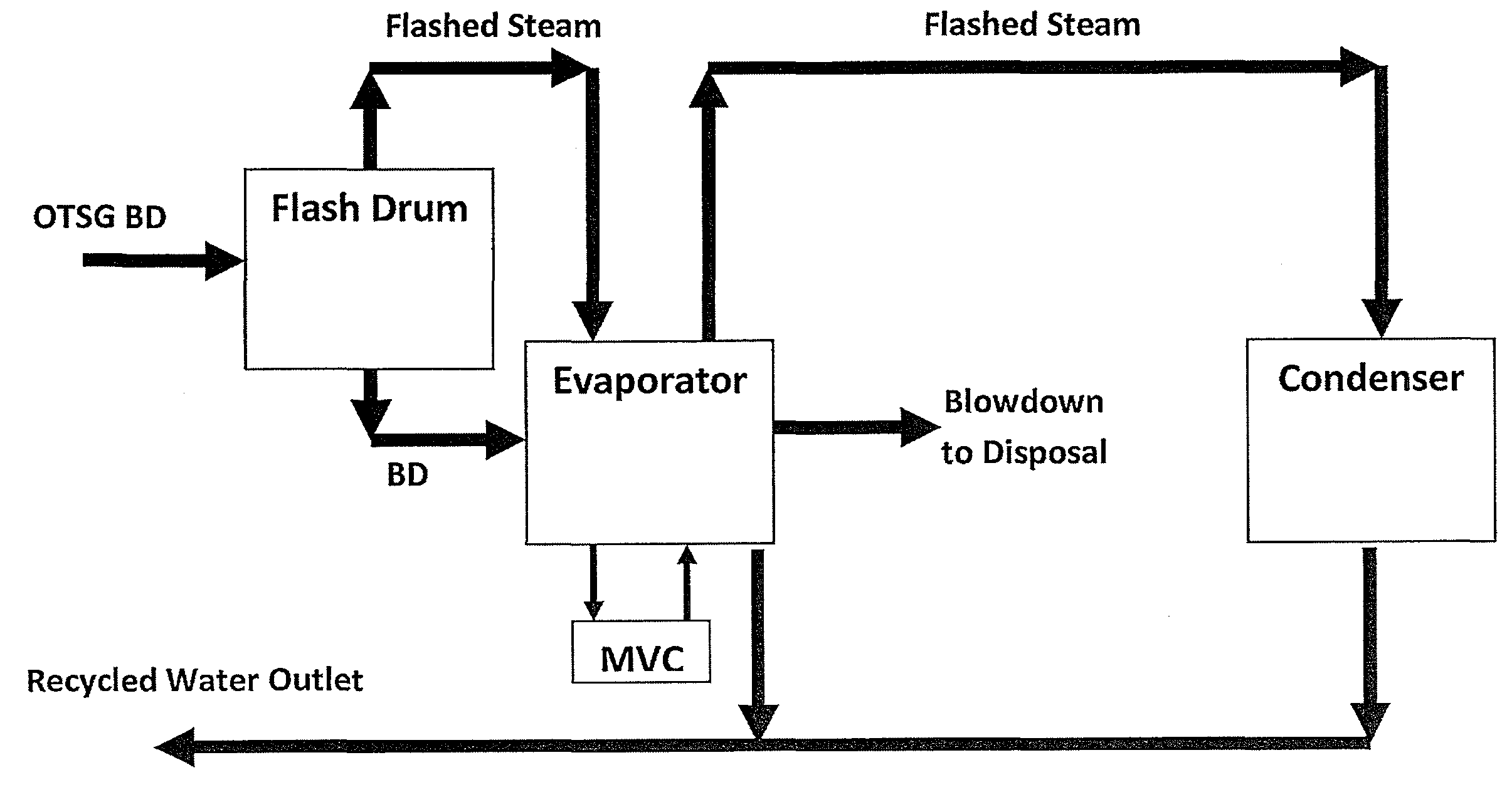
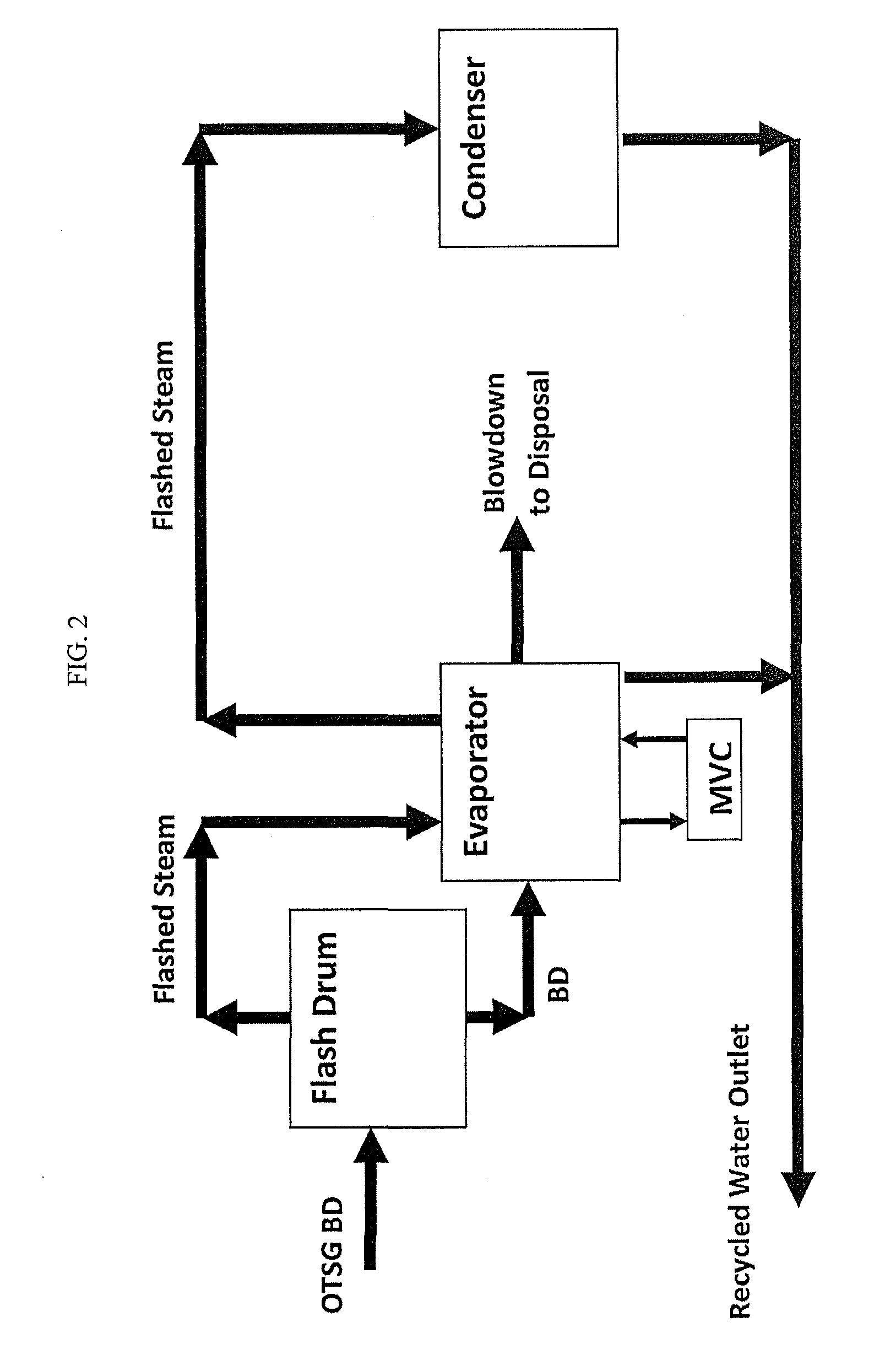
[0079]In a further embodiment the evaporation system includes a 1) flash drum; 2) primary evaporator; and 3) vapor condenser. (Refer to FIG. 8.) An OTSG Blowdown stream has a flow rate of 200 m3 / h. We compare how this would be treated by the conventional evaporator technology and the inventor's technology.

[0080]In this example, the OTSG blowdown stream is to be recovered with a VTFF evaporator that is designed to operate at 20 cycles of concentration for a water recovery of 95%. We then would have an evaporator system mass balance as:[0081]OTSG Blowdown: 200 m3 / h[0082]Distillate: 190 m3 / h[0083]Evaporator Blowdown: 10 m3 / h

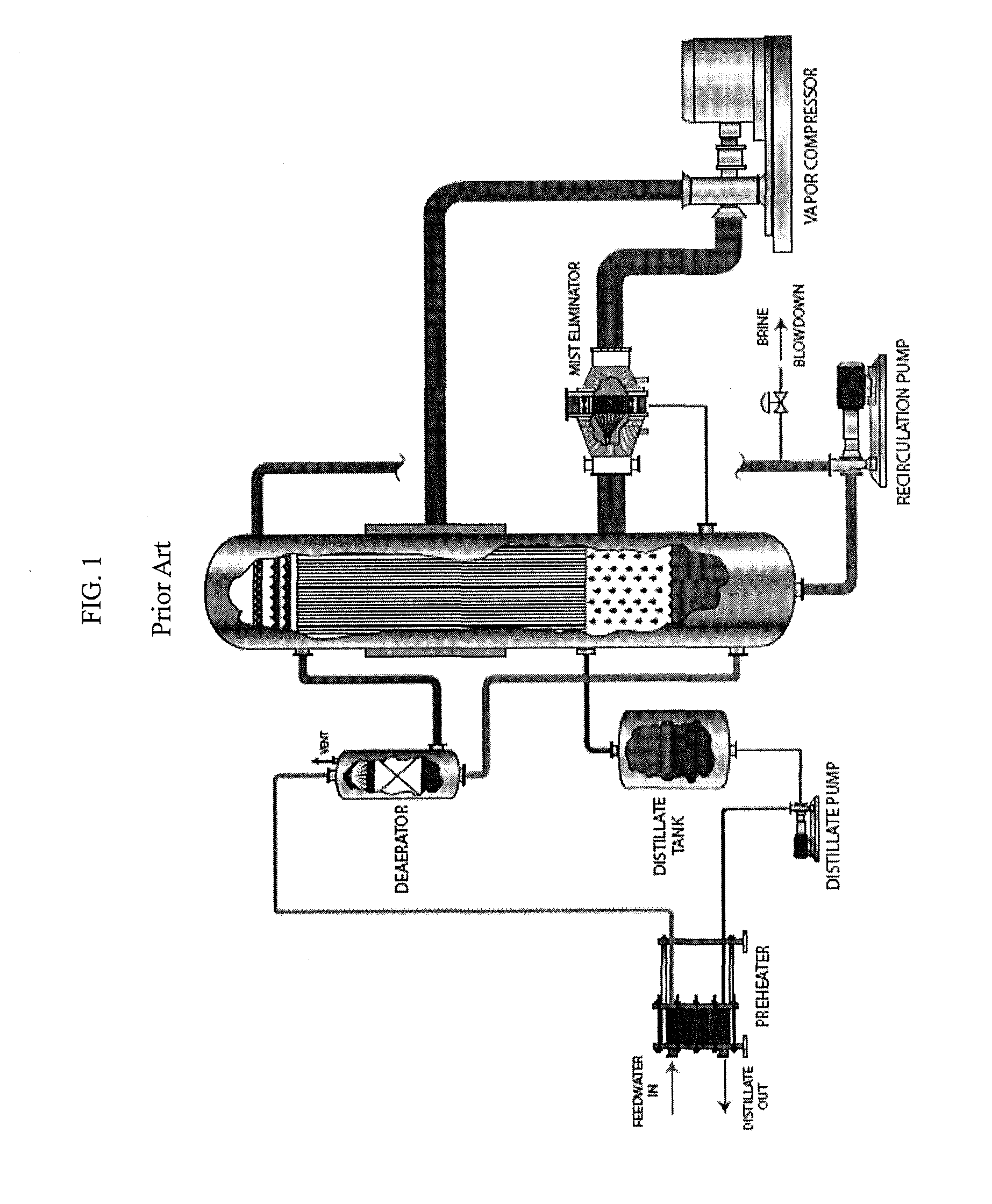
[0084]First consider the conventional evaporator technology. The OTSG blowdown is sent through the BFW preheater and then the trim cooler to deliver the stream to the evaporator at 90° C. (Refer to FIG. 7.) Considering a specific energy requirement for the MVC design of 15 kW·hr / m3 of distillate, the operating power requirement for such a system would calc...


PUM

PropertyMeasurementUnit
boiling temperatureaaaaaaaaaa
temperatureaaaaaaaaaa

Abstract

We provide an evaporation based zero-liquid discharge method for generation of steam for enhanced oil recovery (EOR) processes utilizing once-through steam generators (OTSGs). The method includes feeding the OTSG(s) with produced water, vaporizing a fraction of this water for steam injection and blowing down the balance of the water. This water, referred to as OTSG blowdown, can be flashed to produce a vapor stream and a liquid that is fed to a mechanical vapor compression (MVC) evaporative process. The latent energy contained in the vapor stream generated by the upstream flash is beneficially recycled to substantially reduce or eliminate the energy consumption of the MVC process. The evaporative process can be used to reduce the liquid waste for disposal or eliminate the need for liquid disposal by achieving zero liquid discharge.

Description

CROSS-REFERENCE TO RELATED APPLICATIONS[0001]This application claims priority to U.S. Provisional Patent Application No. 61 / 738,652, filed on Dec. 18, 2012. That application is incorporated by reference herein.STATEMENT REGARDING FEDERALLY SPONSORED RESEARCH OR DEVELOPMENT[0002]Not applicable.BACKGROUND OF THE INVENTION[0003]Several enhanced oil recovery (“EOR”) methods have been demonstrated to have the ability to produce oil from reserves that would otherwise be inaccessible due to their depth below ground-level. Among these methods, thermal EOR techniques in particular have been proven to be effective for oil recovery; these processes often use once-through steam generators (“OTSGs”) to produce the high pressure injection stream necessary for the process.[0004]OTSGs typically produce a steam that is between 50% and 90% quality and, in some cases, requires the liquid phase from the vapor phase prior to injection to the reservoir. In such processes, the blowdown stream is often unf...

Claims


Application Information

Patent Timeline
Patent Type & Authority Applications(United States)
IPC IPC(8): C02F1/04E21B43/40E21B43/24C02F1/06
CPCC02F1/06C02F1/041E21B43/24E21B43/40C02F1/441C02F1/20C02F2103/10C02F2301/046C02F2301/066C02F2301/08C02F2303/10C02F1/042C02F1/04C02F2101/32C02F2103/365F22B29/06Y02W10/30E21B43/35
Inventor MANDIGO, GREGORY J.BJORKLUND, DANIEL P.
Owner AQUATECH INT LLC
Why Eureka
Try Eureka