Stabilizer link and manufacturing method therefor

a technology of stabilizer link and manufacturing method, which is applied in the direction of shaft assembly, mechanical equipment, transportation and packaging, etc., can solve the problems of excessive pressed sheets, broken thermal caulking portion b>42/b>, and insignificant improvement so as to improve the accuracy of centering of the ring member, reduce the concentration of stress, and improve the effect of stud releasing load

Active Publication Date: 2015-01-01
NHK SPRING CO LTD
View PDF5 Cites 14 Cited by
  • Summary
  • Abstract
  • Description
  • Claims
  • Application Information

AI Technical Summary

Benefits of technology

[0027]According to the stabilizer link or the manufacturing method therefor of the present invention, there is less concentration of stress, the stud releasing load can be improved, the accuracy of centering of the ring member can be improved, and other effects can be obtained.

Problems solved by technology

However, in the heat caulking method, a heat caulking portion 42 made of resin is exposed to the outside, and therefore, there is a problem in that the thermal caulking portion 42 is broken by adhering strong acid or by contacting a foreign substance.
Moreover, there is a problem in that the stud releasing load is not drastically improved, since formation position of the heat caulking portion 42, etc., is seriously constrained.
Therefore, the ball sheet is excessively pressed, and a positional relationship between the ball sheet and the ball stud is not appropriately ensured, and frictional force therebetween is unstable.
As a result, there is a problem in that torque characteristics, etc., are unstable.

Method used


Image

  • Stabilizer link and manufacturing method therefor
  • Stabilizer link and manufacturing method therefor
  • Stabilizer link and manufacturing method therefor

Examples


Embodiment Construction

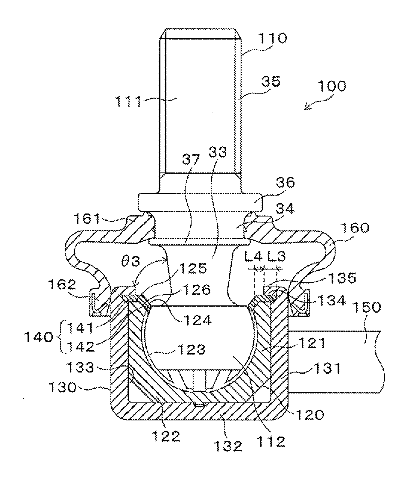
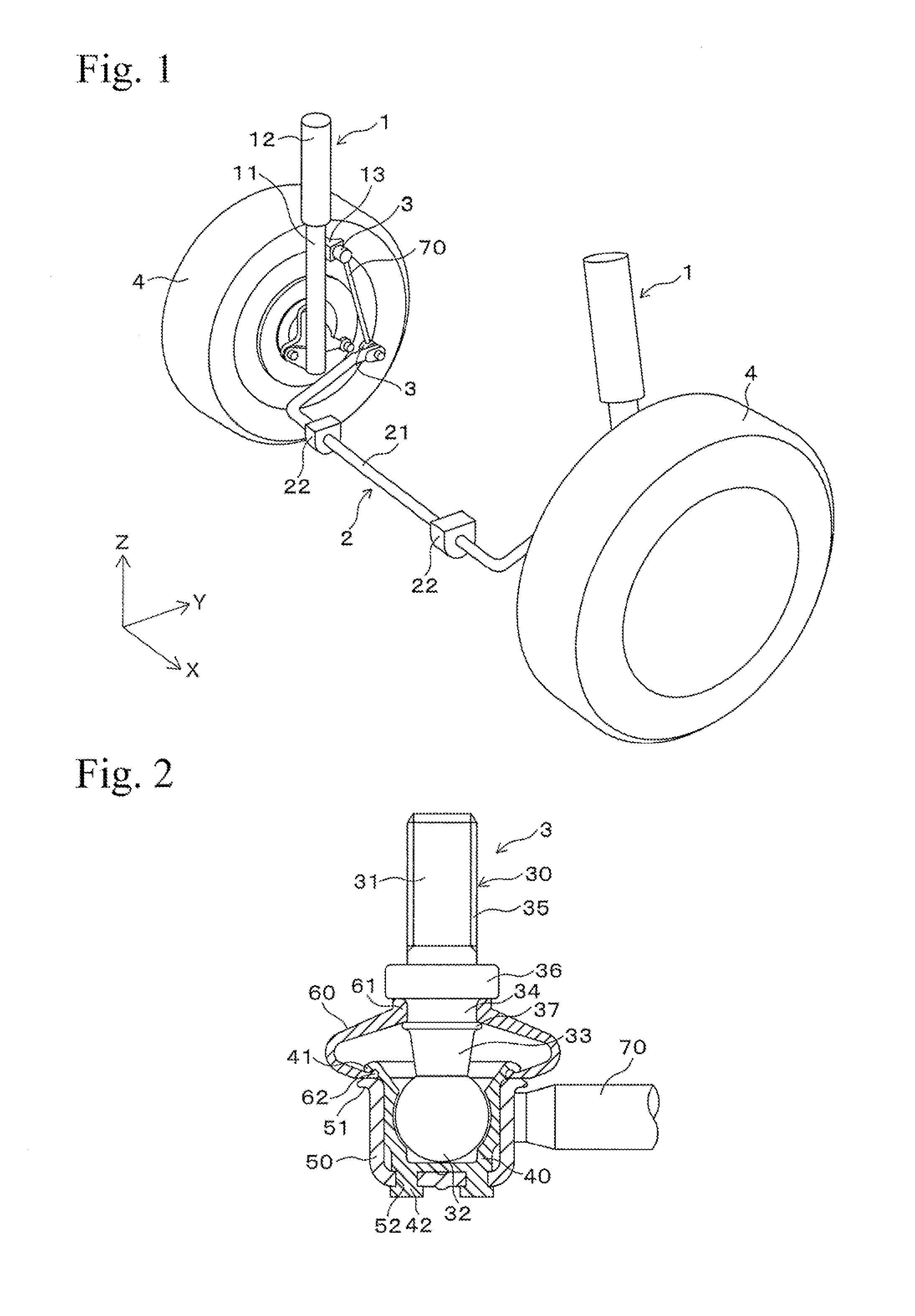
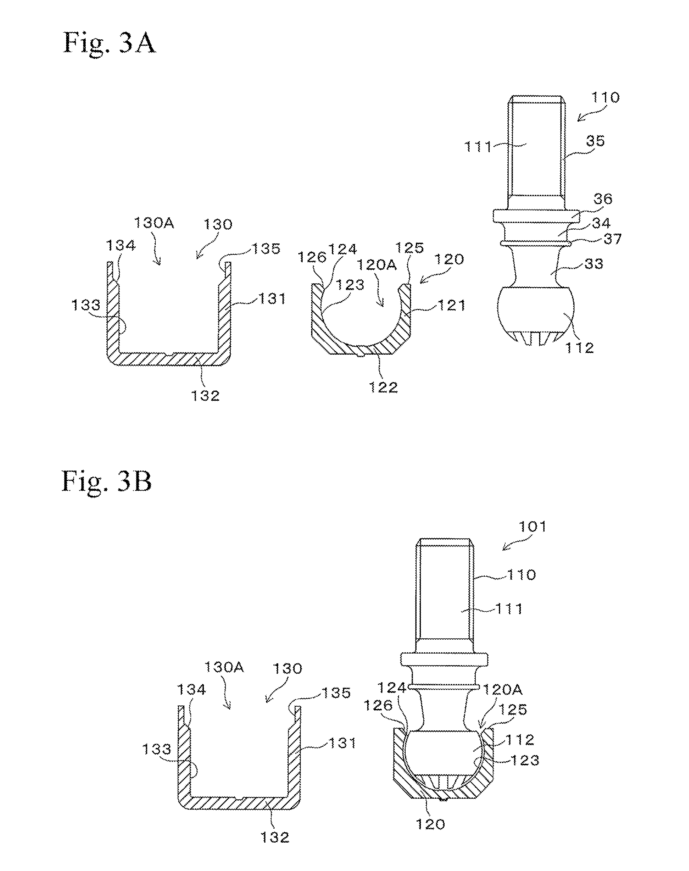
[0038]In the following, an embodiment of the present invention will be explained with reference to the Figures. FIGS. 3 to 5 are side cross sectional views showing each process of a manufacturing method for stabilizer link according to an embodiment of the present invention. FIG. 8 is a side cross sectional view showing a schematic structure of a stabilizer link produced by a manufacturing method for stabilizer link according to an embodiment of the present invention. With respect to the stabilizer link 100 in present embodiments, the similar members to those of the stabilizer link 3 shown in FIG. 2 are represented by the same reference numerals, and the explanations thereof are omitted.

[0039]First, a ball stud 110, a ball sheet 120 and a housing 130 as shown in FIG. 3A, for example are prepared, and a ring member 140 shown in FIG. 6 is prepared.

[0040]The ball stud 110 has a stud portion 111 and a ball portion 112 made of metal and integrally molded, for example. The stud portion 11...


PUM

PropertyMeasurementUnit
inclined angleaaaaaaaaaa
diameteraaaaaaaaaa

Abstract

A stabilizer link and a manufacturing method therefor in which there is less concentration of stress, the stud releasing load is improved, and the accuracy of centering of the ring member is improved. A second subassembly is formed by inserting a ball seat of a first subassembly into a ball seat receiving portion of a housing and by arranging a ring member at an opening side of the ball seat. A stopper base portion is abutted to an opening end surface of the ball seat. An outer peripheral end portion taper surface has a taper shape in which a diameter is increased toward an opening side in an axial direction, in a stopper base portion and it is abutted to a slope portion for a stopper base of the housing. An opening side of the ball seat is pressed through the ring member by caulking inwardly a caulking portion.

Description

TECHNICAL FIELD[0001]The present invention relates to a stabilizer link for vehicles such as automobiles, and in particular, relates to an improved caulking for securing stud releasing load.BACKGROUND ART[0002]A stabilizer is a ball joint part connecting an arm or a strut of a suspension apparatus and a stabilizer apparatus. FIG. 1 is a perspective view showing a schematic structure of a front side wheel of a vehicle. Each suspension apparatus 1 is provided at left and right tires 4 and has an arm 11 and a cylinder 12. A lower end portion of the arm 11 is fixed at a bearing supporting a shaft of the tire 4. The cylinder 12 is elastically movable relatively to the arm 11. A bracket 13, to which a stabilizer link 3 is mounted, is provided at the arm 11. The suspension apparatus 1 supports the weight of a vehicle body that is applied to the tire 4. A stabilizer apparatus 2 is equipped with a bar 21 that is approximately U-shaped, and the stabilizer apparatus 2 is mounted to the vehicle...

Claims


Application Information

Patent Timeline
Patent Type & Authority Applications(United States)
IPC IPC(8): B60G21/055B60G7/00F16C11/06
CPCB60G21/0551B60G7/005F16C11/0695F16C11/0685F16C11/06B60G21/055B60G2204/1224B60G2204/416F16C11/0623F16C2226/52Y10T29/49648B60G2204/42B60G2204/4404B60G2206/82092F16C11/0633F16C11/069F16C2208/66F16C2326/05
Inventor KURODA, SHIGERU
Owner NHK SPRING CO LTD
Why Eureka
Try Eureka