Touch screen, touch panel, display device and electronic device

a display device and touch screen technology, applied in the field of touch screen, can solve the problems of reducing power consumption, reducing requiring a relatively large amount of light, so as to reduce the luminance of an image or picture on the back surface of the touch screen, suppress the effect of broken lines, and increase the density of wires including column wires and row wires

Active Publication Date: 2015-01-01
TRIVALE TECH LLC
View PDF21 Cites 56 Cited by
  • Summary
  • Abstract
  • Description
  • Claims
  • Application Information

AI Technical Summary

Benefits of technology

[0028]In the touch screen according to the present invention, since the normal lines of the curved portion of the reflected-light distribution pattern head for all directions, intense reflected light in the specific direction, which is caused when illuminated by spot-like external light can be made invisible.
[0029]Since a predetermined plural number of the column wires are electrically connected to form a plurality of column-direction bundle wires and a predetermined plural number of the row wires are electrically connected to form a plurality of row-direction bundle wires, effect of broken line can be suppressed. Further, since a gap is provided in the bundle wires, a decrease in the luminance of an image or picture on the back surface of the touch screen can be prevented. Further, since the reflected-light distribution pattern includes the curved portion, the density of wires including the column wires and the row wires can be increased while ensuring a large distance between the column wires and the row wires, thereby reducing uneven display. Since this can suppress an increase in the inter-wire capacitance that is the parasitic capacitance between the column wires and the row wires, and reduce uneven display, it becomes possible to detect the touch capacitance that is the capacitance formed between the indicator, and the column wires and the row wires uniformly and high-sensitively.
[0030]Therefore, a touch screen that has excellent detection accuracy and display quality, and is capable of achieving outstanding visibility even when illuminated by external light can be realized.
[0031]A touch panel according to the present invention includes the touch screen that, as described above, has excellent detection accuracy and display quality, and is capable of achieving outstanding visibility even when illuminated by external light. This can realize the touch panel that can be increased in size without decreasing the sensitivity of detecting the touch capacitance.
[0032]A display device according to the present invention includes the touch panel provided with the touch screen that, as described above, has excellent accuracy of detecting a touch position and display quality, and is capable of achieving outstanding visibility even when illuminated by external light. Therefore, the display device having outstanding visibility can be realized.
[0033]An electronic device according to the present invention includes the touch panel provided with the touch screen that, as described above, has excellent accuracy of detecting a touch position and display quality, and is capable of achieving outstanding visibility even when illuminated by external light. Therefore, the electronic device having outstanding visibility and touch position detection function can be realized.

Problems solved by technology

However, the transparent conducting film such as ITO have a relatively high electric resistance (hereinafter may be referred to as merely “resistance”), which is disadvantageous to increase the size of the touch screen.
Further, since the transparent conducting film such as ITO has a relatively low optical transmittance (hereinafter may be referred to as merely “transmittance”), when the touch screen is illuminated from the back surface side, that is, the opposite side to the user, during use in a liquid crystal display (abbreviated as LCD) or the like, a relatively large amount of light is needed, which is disadvantageous to reduce power consumption.
When thinned metal wires are used as the detection wires and are densely disposed in the operational region of the touch screen, a parasitic capacitance between the detection column wires and the detection row wires (hereinafter may be referred to as “inter-wire capacitance”) largely increases, causing failures including an increase in wiring delay.
Accordingly, when the touch screen is used in combination with a display element disposed opposed to the back surface of the touch screen, uneven luminance and uneven display such as moire occur in a display screen of the display element, and are often viewed as failures to the user.
When a picture is placed opposed to the back surface of the touch screen and the touch screen is used as a digitizer or tablet, uneven luminance occurs in the picture, and is often viewed as a failure to the user.

Method used


Image

  • Touch screen, touch panel, display device and electronic device
  • Touch screen, touch panel, display device and electronic device
  • Touch screen, touch panel, display device and electronic device

Examples


first embodiment

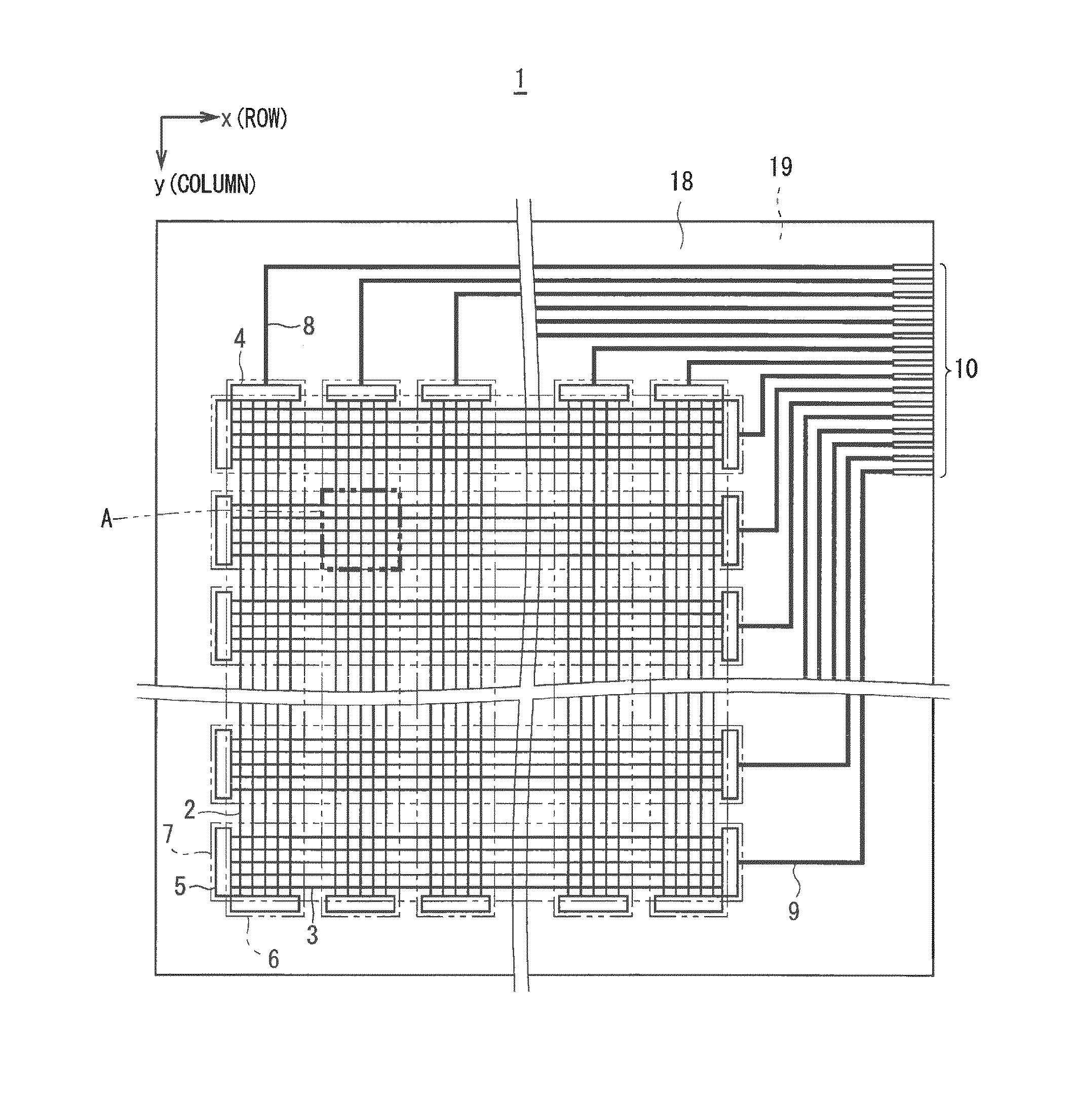
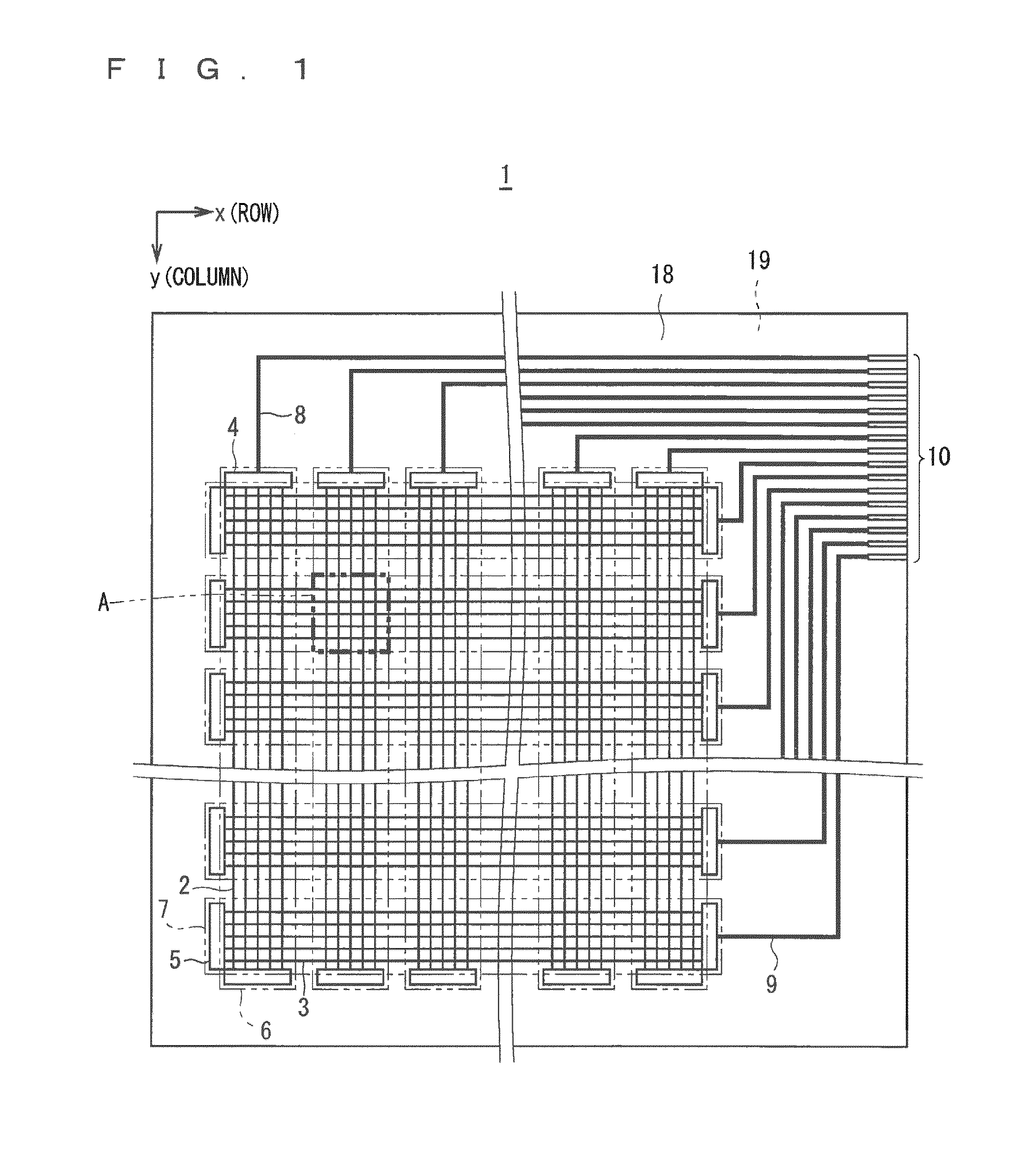
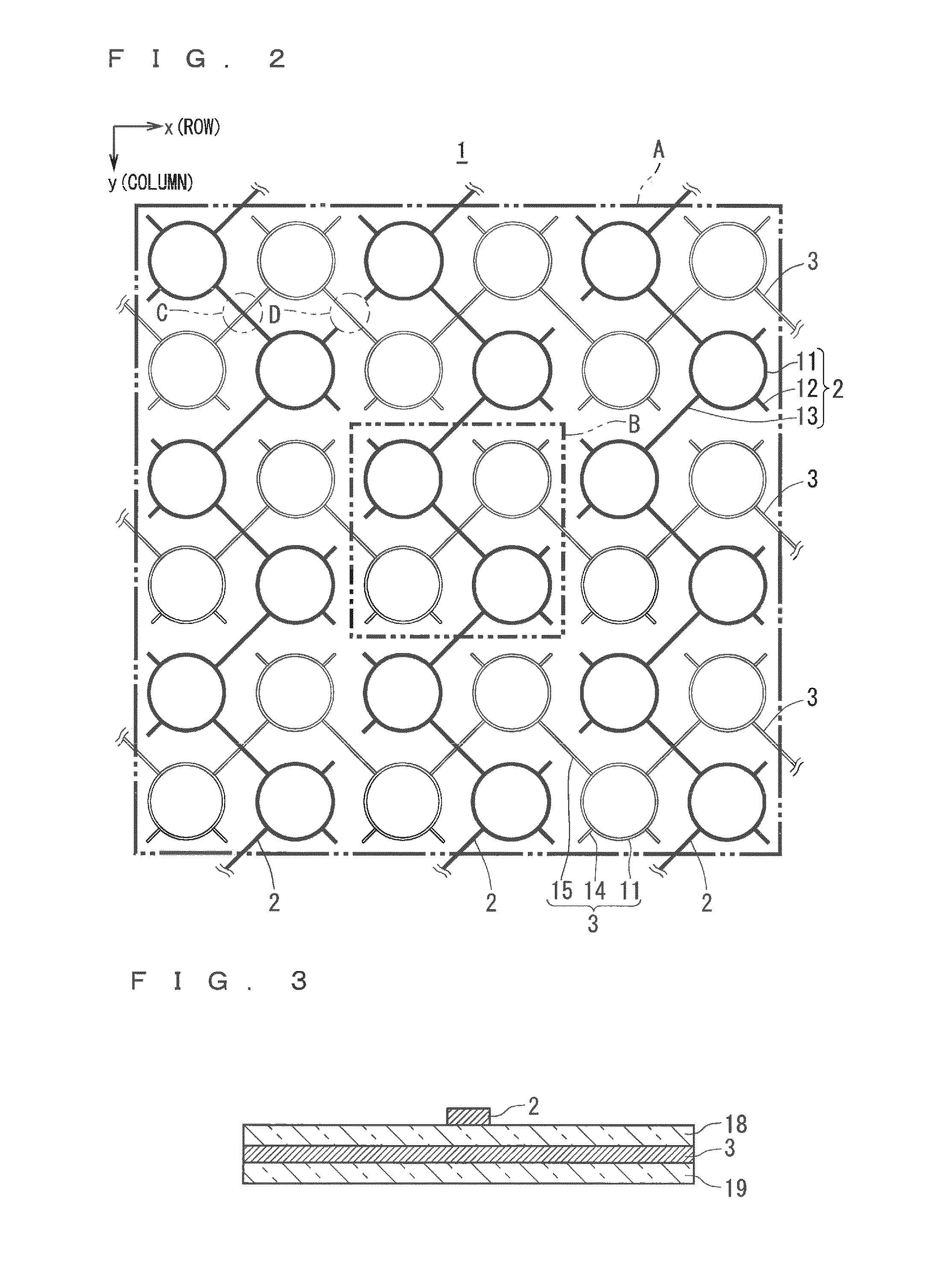
[0064]FIG. 1 is a projection view showing a configuration of a touch screen 1 in accordance with First embodiment of the present invention. FIG. 1 is a projection view when viewed in the direction of a normal line from a front surface side of a transparent base 19. The front surface of the transparent base 19 is a surface facing a user of the transparent base 19, and the direction of the normal line from the front surface of the transparent base 19 is the direction perpendicular to the surface facing the user of the transparent base 19. The “projection view” will be hereinafter referred to a projection view when viewed in such a direction, that is, the direction of the normal line from the front surface side of the transparent base 19. It is assumed that the surface of the transparent base 19, on which detection wires 2 and 3 are disposed is planar. In the case where the surface of the transparent base 19 is curved, projection on a plane perpendicular to the normal line of the surfa...

second embodiment

[0186]FIG. 17 is a projection view showing a wiring pattern of a touch screen 30 in Second embodiment of the present invention. In the touch screen 30 in this embodiment, thin wires constituting the detection column wires 32 and the detection row wires 33 are curved lines including the closed reflected-light distribution pattern 11.

[0187]Specifically, as shown in FIG. 17, in this embodiment, the linear thin wire connecting the reflected-light distribution pattern of the touch screen 1 in First embodiment in FIG. 2 is replaced with a corrugated thin wire. This can further decrease the inter-wire capacitance.

[0188]Since merely replacement of the linear thin wire with the corrugated thin wire increases the resistance of the detection wires 32, 33, measures for reducing the resistance, such as increasing the thickness of the thin wire and the use of a low resistance material may be also adopted to balance the increase in resistance and the effect of reducing capacitance.

[0189]When the p...

third embodiment

[0199]FIG. 19 is a projection view showing a wiring pattern of a touch screen 40 in Third embodiment of the present invention. Also in this embodiment, detection wires 42 and 43 are configured to function as the reflected-light distribution pattern. In this embodiment, as shown in FIG. 19, the detection wires 42 and 43 do not use the closed thin wire, that is, the thin wire having the closed median line.

[0200]Specifically, the detection wires 42 and 43 are not straight line, but corrugated curved thin wires connecting 90 degrees arc-shaped thin wires having projections and depressions. The projection is opposed to the depression. When the selection procedure of the reflected-light distribution pattern in First embodiment is applied to wires in the region B in FIG. 19, two corrugated thin wires connected in a substantially cross gammadion shape at the center of the region B are selected according to the case (d) with four end points. Further, four 90 degrees arc-shaped thin wires tha...


PUM


Abstract

Detection column wires and detection row wires are configured of thin wires made of a conductive material having light reflectivity, such as a metal or alloy including silver and aluminum. A predetermined plural number of detection column wires are electrically connected to form a plurality of column-direction bundle wires. A predetermined plural number of detection row wires are electrically connected to form a plurality of row-direction bundle wires. A reflected-light distribution pattern is further provided. When viewed in a direction vertical to the surface of the touch screen, the reflected-light distribution pattern includes a curved portion, and the normal lines of the curved portion head for all directions.

Description

TECHNICAL FIELD[0001]The present invention relates to a touch screen, a touch panel, a display device, and an electronic device.BACKGROUND ART[0002]Touch panels have been widely known as a device for detecting and outputting the position on a touch screen, which is indicated by an indicator such as a user's finger or a pen (hereinafter may be referred to as “touch position”). A plurality of detection methods for detecting the touch position in the touch panel have been known. Examples of capacitive touch panels include a projected capacitive touch panel.[0003]The projected capacitive touch panel can detect the touch position even when a surface of the touch screen on the side of the user (hereinafter may be referred to as “front surface”) is covered with a protective plate such as a glass plate having a thickness of about a few mm. The projected capacitive touch panel has the protective plate disposed on the front surface and has no movable part, and therefore, is advantageously rob...

Claims


Application Information

Patent Timeline
Patent Type & Authority Applications(United States)
IPC IPC(8): G06F3/044H05K1/02
CPCH05K1/0274H05K1/0298H05K2201/0302H05K2201/10128H05K2201/10151G06F3/044G06F3/041G06F2203/04112G06F3/0412G06F3/0445G06F3/0446G02F1/13338G06F3/047H05K1/09
Inventor NISHIOKA, TAKAHIRONAKAGAWA, NAOKIAGARI, MASAFUMIONO, TAKESHIMORI, SEIICHIRO
Owner TRIVALE TECH LLC
Why Eureka
Try Eureka