Wavelength swept source apparatus and controlling method thereof

a light source and wavelength technology, applied in the direction of light demodulation, instruments, semiconductor lasers, etc., can solve the problems of high unit cost of the apparatus, low reliability and large volume of the bulk optics type apparatus

Inactive Publication Date: 2015-01-01
ELECTRONICS & TELECOMM RES INST
View PDF2 Cites 12 Cited by
  • Summary
  • Abstract
  • Description
  • Claims
  • Application Information

AI Technical Summary

Benefits of technology

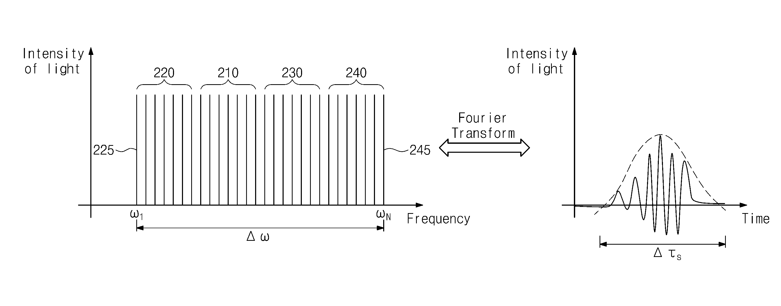
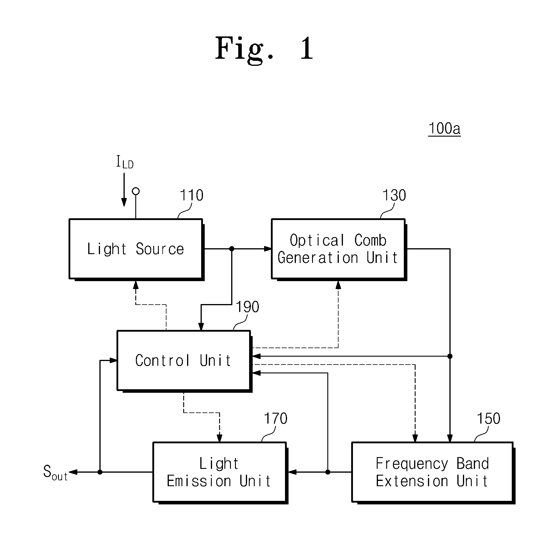
[0011]The inventive concept provides a wavelength swept source apparatus having a different structure from that of a typical wavelength swept source apparatus, and a method for controlling thereof. According to an embodiment of the inventive concept, limitations of the typical wavelength swept source apparatus may be overcome. That is, the wavelength swept source apparatus according to the inventive concept may sequentially emit a plurality of light rays having different frequencies stably and rapidly. Furthermore, according to the inventive concept, the wavelength swept source apparatus may be controlled so that wavelength sweeping is appropriately performed.

Problems solved by technology

However, the bulk optics type apparatus needs precise optical alignment and has a large volume.
Moreover, the bulk optics type apparatus has low reliability due to its strong mechanical vibration.
However, the fiber optics type apparatus has a large volume and includes a large number of components, accordingly, has high unit cost of the apparatus.
However, according to the semiconductor integrated optical element type apparatus, an oscillation mode may be discontinuously switched while a wavelength is tuned, i.e., a mode hopping phenomenon may occur.
Moreover, according to the semiconductor integrated optical element type apparatus, a method to change a frequency is complicated.
However, the typical implementation types have limitations in terms of a frequency changing speed of output light and operation stability.

Method used


Image

  • Wavelength swept source apparatus and controlling method thereof
  • Wavelength swept source apparatus and controlling method thereof
  • Wavelength swept source apparatus and controlling method thereof

Examples


Embodiment Construction

[0037]The above-described characteristics and the following detailed description are merely examples for helping the understanding of the inventive concept. That is, the inventive concept may be embodied in different forms and should not be constructed as limited to the embodiments set forth herein. The following embodiments are merely examples for completely disclosing the inventive concept and for delivering the inventive concept to those skilled in the art that the inventive concept belongs. Therefore, in the case where there are multiple methods for implementing the elements of the inventive concept, the inventive concept may be implemented with any of the methods or an equivalent thereof.

[0038]When it is mentioned that a certain configuration includes a specific element or a certain process includes a specific step, another element or another step may be further included. That is, the terms used herein are not for limiting the concept of the inventive concept, but for describin...


PUM

PropertyMeasurementUnit
lengthaaaaaaaaaa
lengthaaaaaaaaaa
wavelength sweptaaaaaaaaaa

Abstract

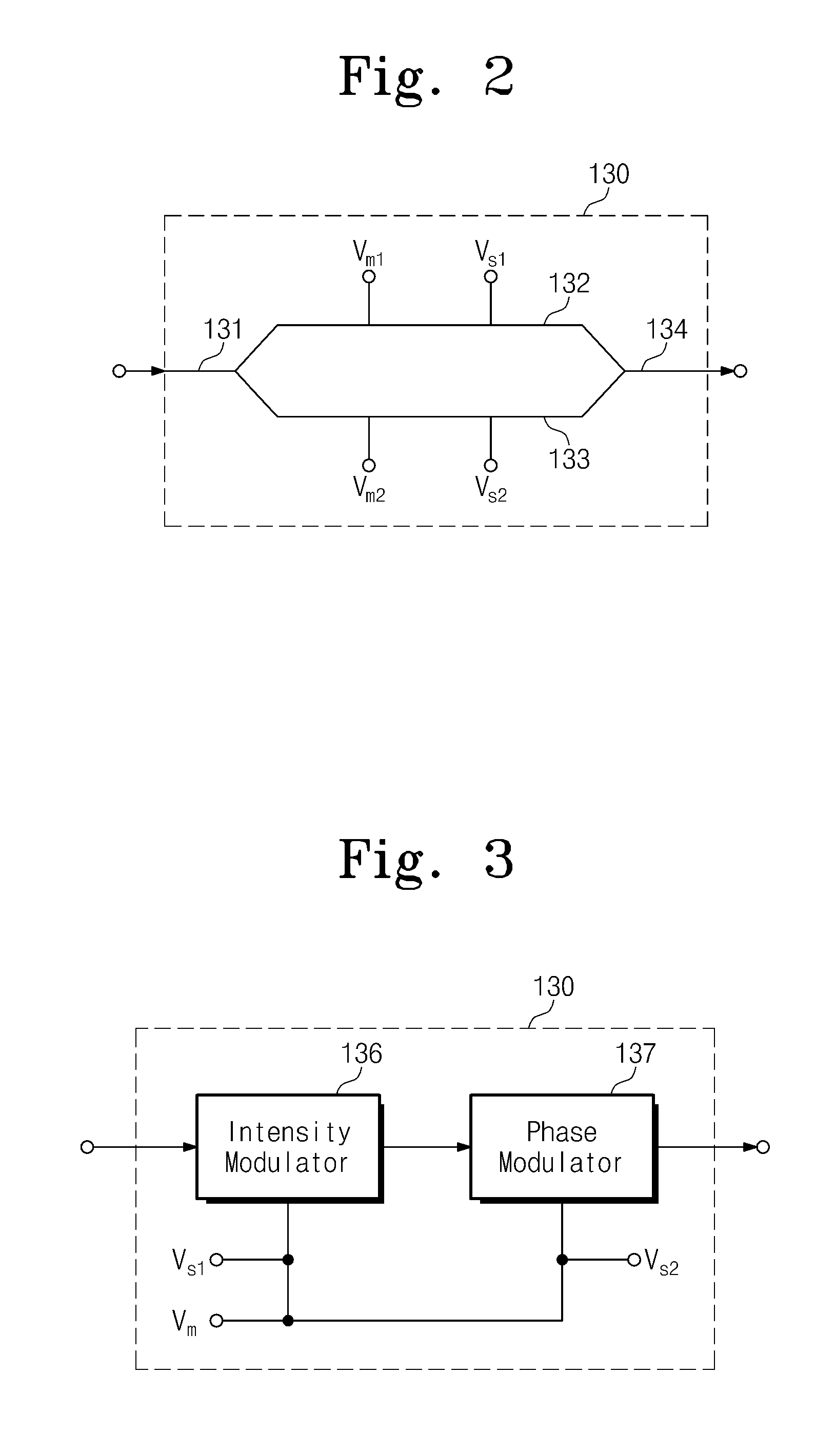
Provided are a wavelength swept source apparatus and a method for controlling thereof. According to the provided apparatus and method, single mode light is generated, a basic optical comb is generated by modulating the generated single mode light, and a plurality of optical combs having different a frequency band from that of the basic optical comb is generated by modulating the plurality of light rays. The plurality of light rays and light rays included in the plurality of optical combs are sequentially emitted according to frequencies of the plurality of light rays and the light rays included in the plurality of optical combs. A value of a control variable is adjusted based on a characteristic of the generated single mode light, the plurality of light rays, the light rays included in the plurality of optical combs, and the emitted light rays.

Description

CROSS-REFERENCE TO RELATED APPLICATIONS[0001]This U.S. non-provisional patent application claims priority under 35 U.S.C. §119 of Korean Patent Application No. 10-2013-0073721, filed on Jun. 26, 2013, the entire contents of which are hereby incorporated by reference.BACKGROUND OF THE INVENTION[0002]1. Technical Field[0003]The inventive concept relates to a wavelength tunable light source apparatus, and more particularly, to a wavelength swept source apparatus for sequentially and rapidly emitting a plurality of rays having different frequencies and a controlling method thereof.[0004]2. Description of Related Art[0005]A wavelength swept source apparatus sequentially emits a plurality of rays having different frequencies. The wavelength swept source apparatus is used in various fields such as the fields of a real-time optical coherent tomography (OCT) instrument for monitoring an industrial process, a medical three-dimensional OCT instrument, a light source for optical communication, ...

Claims


Application Information

Patent Timeline
Patent Type & Authority Applications(United States)
IPC IPC(8): G02F1/35
CPCG02F1/3532H01S5/0687G02F1/383G02F2/00
Inventor KWON, OH KEELEE, CHUL-WOOKHAN, YOUNG-TAKSHIN, JANG UKSONG, MINHYUPOH, KWANG RYONG
Owner ELECTRONICS & TELECOMM RES INST
Why Eureka
Try Eureka