Fluoride phosphor and light emitting device using the same and method of manufacturing the fluoride phosphor
a technology of fluoride phosphor and light emitting device, which is applied in the direction of luminescent compositions, instruments, chemistry apparatuses and processes, etc., can solve the problems of difficult implementation of reliability, poor water resistance of conventional fluoride phosphors activated with tetravalent mn, and inability to achieve satisfactory durability in a long-term reliability test. , to achieve the effect of good light emission characteristics, good water resistance and good light emission characteristics
- Summary
- Abstract
- Description
- Claims
- Application Information
AI Technical Summary
Benefits of technology
Problems solved by technology
Method used
Image
Examples
embodiments
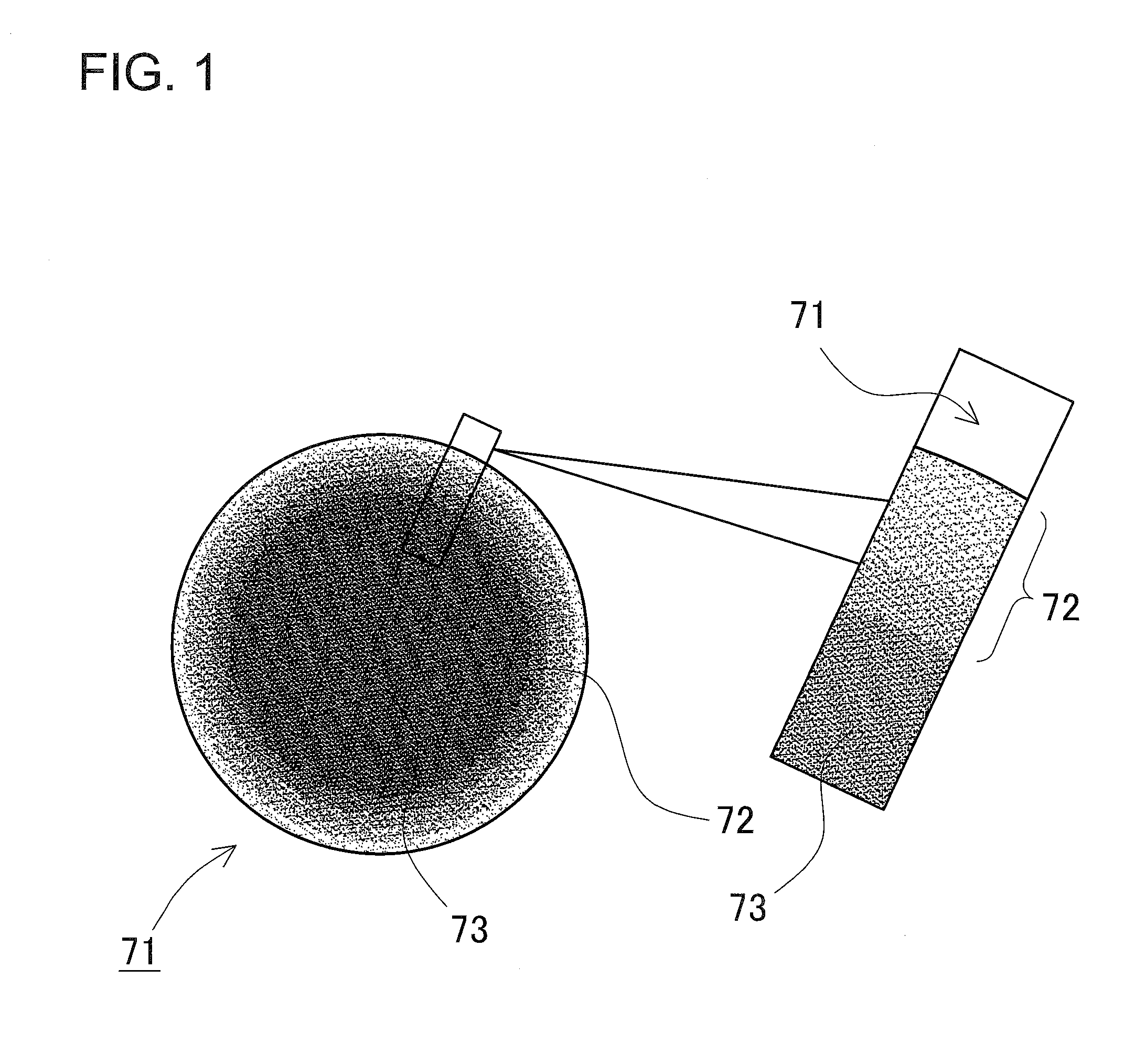
[0031]In reliability tests of fluoride phosphors under humid conditions, tetravalent Mn serves as an activator and are located on the surface of the phosphor particles react with water to create MnO2 which has a dark color, resulting in degradation of the luminance. As a result of intensive studies on the surface composition of fluoride phosphors, the present inventor found that forming a surface region with lower tetravalent Mn on the phosphor particles while maintaining the same composition as a phosphor allows for an improvement in the water resistance of the phosphor.
[0032]The fluoride phosphor according to the present embodiment can be represented by a general formula K2[M1-aMn4+aF6] (wherein M is at least one selected from group-IV elements of Ti, Zr, and Hf and group IVB elements of Si, Ge, Sn, and a is 0
example 1
[0066]Next, processes of manufacturing the fluoride phosphors according to Example 1 will be described below. In order to obtain the charge composition ratio shown in Table 2, 12.27 g of 40 wt % H2SiF6 aqueous solution was weighed and 150 g of 55 wt % HF aqueous solution was added to prepare the solution D. Meanwhile, the solution E was prepared by weighing 2.66 g of KHF2 and dissolving it in 60 g of 55 wt % HF aqueous solution. Next, while stirring the solution D, 30.0 g of the phosphor core obtained in Comparison Example 1 was charged in the solution D, then 1.5 g of 30 wt % H2O2 aqueous solution was added to reduce the eluted Mn4+ into Mn2+ to suppress the generation of fluoride complex [MnF6]2−. In the present example, hydrogen peroxide (H2O2) is employed as the reducing agent, but in a method of manufacturing a phosphor according to the present example, the reducing agent is not limited to hydrogen peroxide and other reducing agents such as oxalic acid can also be employed.
[MnF...
examples 2 to 9
[0068]The fluoride phosphors according to Examples 2 to 9 were formed in a similar manner as in Example 1, except for changing the charging composition ratio and the charged amounts which are shown in Table 2. The emission luminance characteristics of the respective fluoride phosphors obtained in this manner and the emission luminance characteristics after evaluating the water resistance are shown in Table 3.
TABLE 3Luminous FluxChromaticityRelativeChromaticityRelativeMaintainingCoordinatesLuminanceCoordinatesLuminanceRatexy(%)xy(%)(%)COMPARISON0.6770.313100.00.6780.31260.460.4EXAMPLE 1EXAMPLE 10.6770.312100.00.6770.31296.196.1EXAMPLE 20.6770.312100.00.6770.31296.996.3EXAMPLE 30.6770.31299.70.6780.31294.594.7EXAMPLE 40.6770.31297.40.6770.31297.4100.0EXAMPLE 50.6770.31297.10.6780.31296.399.2EXAMPLE 60.6770.31394.50.6770.31296.3101.9EXAMPLE 70.6770.31393.70.6770.31295.3101.7EXAMPLE 80.6770.31292.70.6770.31292.499.7EXAMPLE 90.6770.31291.30.6770.31290.899.4
Emission Luminance Measurement ...
PUM
| Property | Measurement | Unit |
|---|---|---|
| wavelength region | aaaaa | aaaaa |
| temperature | aaaaa | aaaaa |
| temperature | aaaaa | aaaaa |
Abstract
Description
Claims
Application Information
 - R&D
- Intellectual Property
- Life Sciences
- Materials
- Tech Scout
- Unparalleled Data Quality
- Higher Quality Content
- 60% Fewer Hallucinations
Browse by: Latest US Patents, China's latest patents, Technical Efficacy Thesaurus, Application Domain, Technology Topic, Popular Technical Reports.
© 2025 PatSnap. All rights reserved.Legal|Privacy policy|Modern Slavery Act Transparency Statement|Sitemap|About US| Contact US: help@patsnap.com


