Pitch drive systems and methods

a technology of pitch drive and drive system, applied in the direction of motors, engine fuctions, sustainable buildings, etc., can solve the problems of reducing the frequency of manual operation, time and resource consumption, and damage to the diodes, transistors and other electronic components of the electronic converter, so as to reduce the value of circulating current and slow charge

Inactive Publication Date: 2015-01-08
GE RENEWABLE TECH WIND BV
View PDF7 Cites 31 Cited by
  • Summary
  • Abstract
  • Description
  • Claims
  • Application Information

AI Technical Summary

Benefits of technology

[0014]Damaging in-rush currents from the back-up energy storage, which are caused by a relatively high difference in voltage between the back-up energy storage and the DC-link of the electronic converter, may be effectively avoided by high frequency switching. As the back-up energy storage is disconnected and connected to the DC-link with a high frequency, the one or more capacitors of the DC-link capacitor bank are more slowly charged, thus controlling the difference in voltage level between the back-up energy storage and the DC-capacitor bank and, consequently, limiting the value of circulating current.

Problems solved by technology

However, whilst a traditional electrochemical battery releases its energy through processes that limit discharge currents; this is not the case with ultracapacitors.
Thus, when the ultracapacitors are fully charged and the voltage at the DC-link to which they are connected is at or close to zero volts (e.g. because grid voltage is zero or no connection with the electrical grid exists during maintenance operations, so the capacitors at the DC-link are discharged), the ultracapacitors discharge from its initial charge state to zero voltage in a very short time, thus resulting in very high in-rush currents which can damage the diodes, transistors and other electronic components within the electronic converter.
This problem is currently being addressed by manually pre-discharging the energy storage units, which is a time and resource consuming task.
Furthermore, as ultracapacitors are especially used in offshore installations, the frequency of manual operations is further required to be kept at a minimum due to very high costs related to such activities.
As the back-up energy storage is disconnected and connected to the DC-link with a high frequency, the one or more capacitors of the DC-link capacitor bank are more slowly charged, thus controlling the difference in voltage level between the back-up energy storage and the DC-capacitor bank and, consequently, limiting the value of circulating current.

Method used


Image

  • Pitch drive systems and methods
  • Pitch drive systems and methods

Examples


Embodiment Construction

[0022]The system and method disclosed herein provide protection to wind turbine pitch drives from in-rush currents discharged from the back-up energy storage unit during maintenance operations.

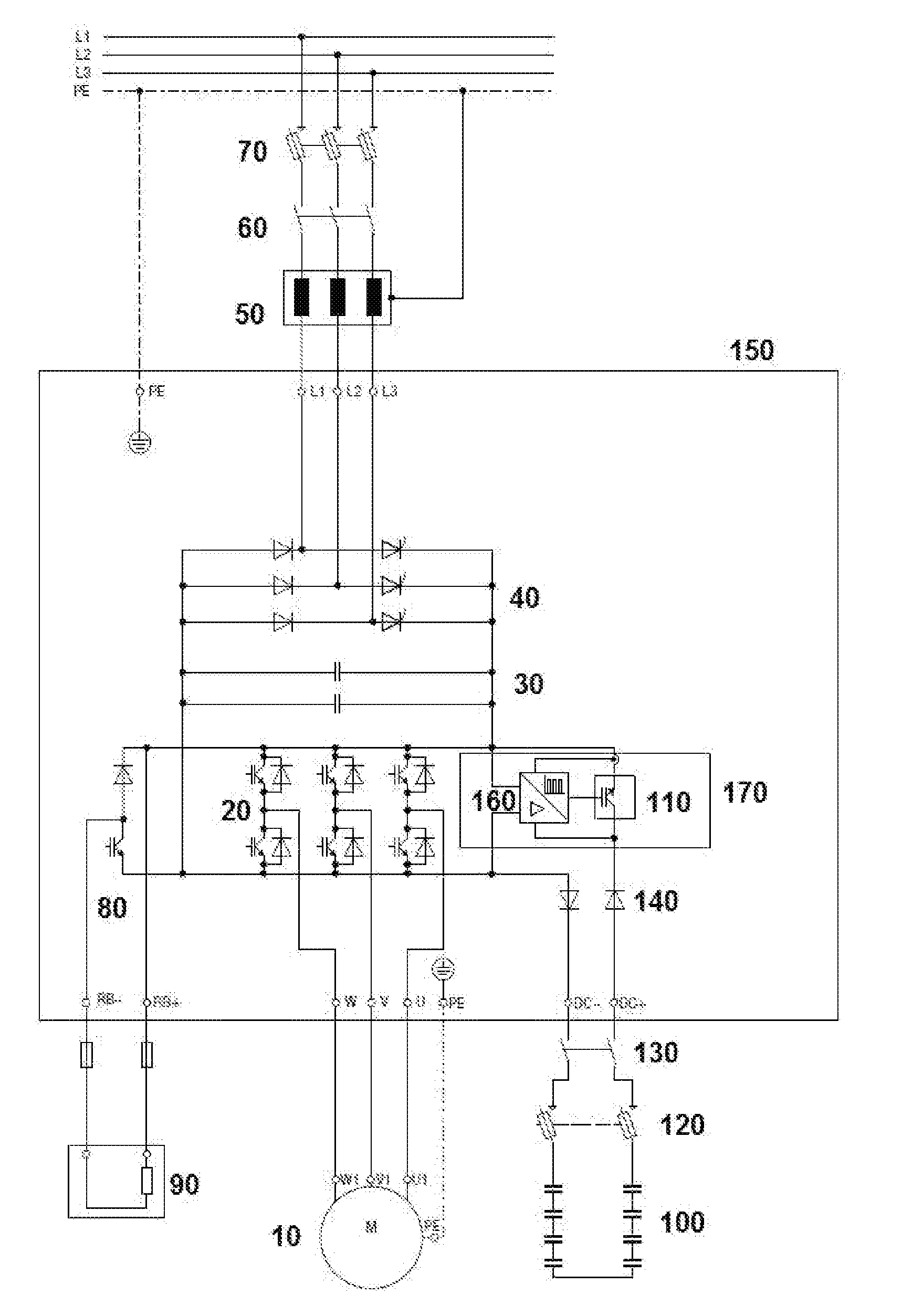
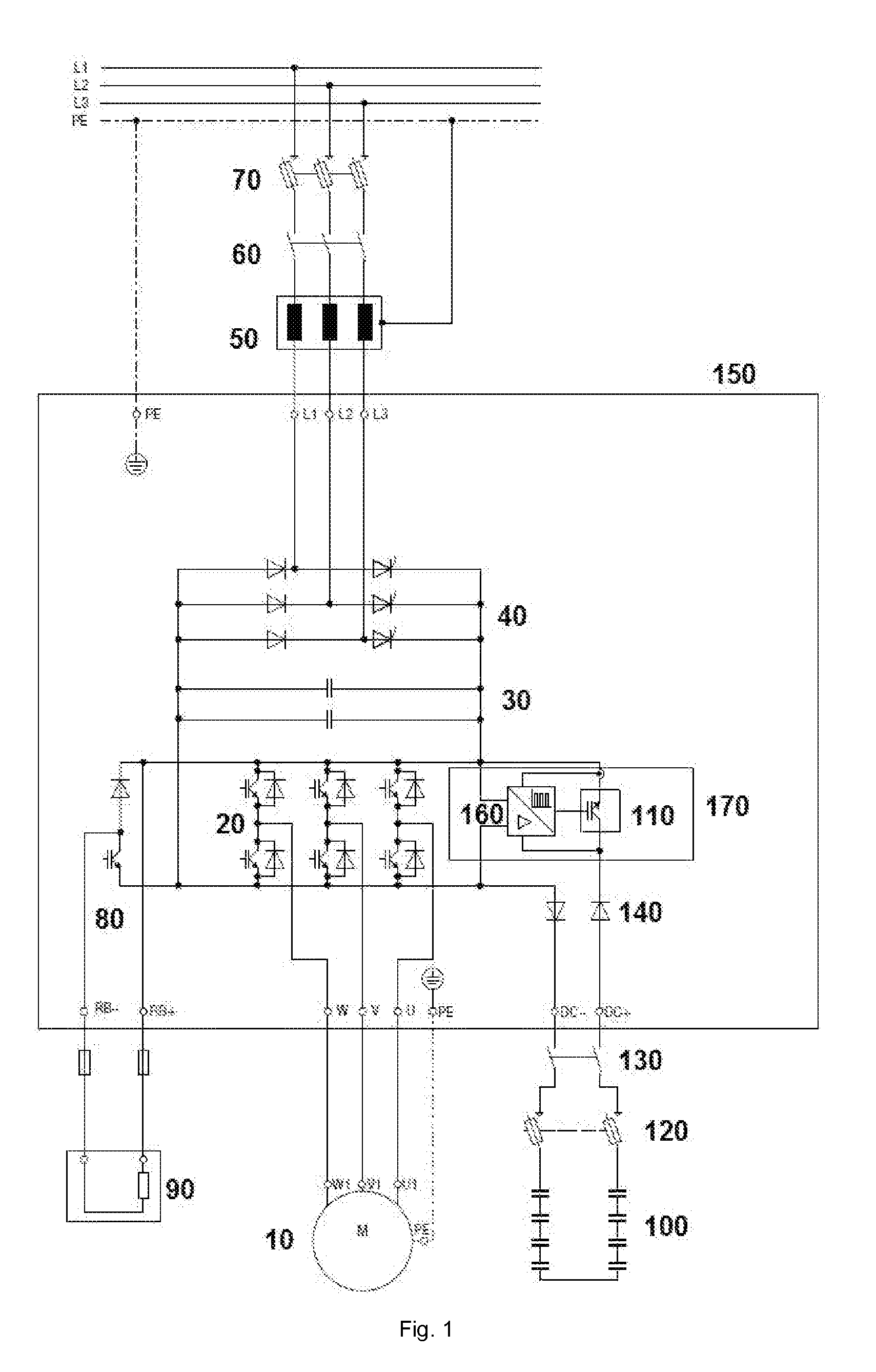
[0023]The embodiment illustrated in FIG. 1 shows a pitch drive electrical system of a wind turbine. The 3 phases lines (W1, V1, U1) of the pitch drive motor (10) are each respectively connected to the 3 phases lines (L1, L2, L3) of the electrical grid, across the pitch drive electronic power converter (150) . This pitch drive electronic converter may comprise a thyristor bridge (40) to rectify AC to DC power, a DC link capacitor bank (30) to stabilise the power and a power stage (20) to invert DC to AC power and a brake chopper (80) to dissipate excess energy, e.g. energy generated by the pitch drive motor (10) when it operates as a generator.

[0024]Other components such as a grid power choke (50), a grid contactor (60) and grid fuses (70) and a braking resistor (90) may also be included and ar...


PUM


Abstract

A wind turbine pitch drive system comprises an electric grid for supplying electrical power, a motor for driving a pitch actuator, an electronic converter for controlling the motor and a back-up energy storage unit for supplying electrical power. The electronic converter comprises a DC-link capacitor bank. The system furthermore comprises a switching device for selectively connecting the DC-capacitor bank link to the back-up energy storage unit, and a frequency generator for controlling the switching device. Also disclosed is a method for protecting a component of the electronic converter.

Description

[0001]This application claims the benefit of European Patent Application 13382279.1 filed on Jul. 5, 2013, the entire contents of which are hereby incorporated by reference for all purposes.[0002]The present disclosure relates to pitch drive systems for rotating one or more rotor blades of a wind turbine around their longitudinal axes.BACKGROUND ART[0003]Wind turbines comprise pitch drives for rotating the rotor blades longitudinally in order to control the power extracted by the rotor and to mitigate the loads suffered by the structure as wind speed changes. By continuously adjusting the blade pitch angle, the aerodynamic angle of attack is adapted so that the influence of the wind on the blades can be increased or decreased. Each blade may have its independent pitch drive. Alternatively, a common pitch drive may be provided for a plurality of blades.[0004]Blade feathering, consisting of turning the blades about 90 degrees about their longitudinal axis, is performed during emergenc...

Claims


Application Information

Patent Timeline
Patent Type & Authority Applications(United States)
IPC IPC(8): H02J11/00F03D9/00F03D7/02
CPCH02J11/00F03D9/003F03D7/0224F05B2260/42F03D80/00F03D9/255H02J9/062Y02B10/70Y02E10/72Y02E10/76F03D7/00
Inventor PALOMARES RENTERO, PEDRORUJAS, ALEJANDROORTIZ DE LANDAZURI, HECTOR
Owner GE RENEWABLE TECH WIND BV
Why Eureka
Try Eureka