Hot Surface Igniter With Fuel Assist

a technology of fuel assist and hot surface, which is applied in the direction of burner control devices, combustion regulation, burners, etc., can solve the problems of unburned fuel, reduced combustion efficiency, and undesirable combustion performance,

Inactive Publication Date: 2015-01-08
PEERLESS MFG CO
View PDF4 Cites 13 Cited by
  • Summary
  • Abstract
  • Description
  • Claims
  • Application Information

AI Technical Summary

Benefits of technology

[0010]In accordance with one aspect of the present invention, a large-scale combustion system has a fuel line having a burner end, a burner at the burner end of the fuel line, a source of fuel flowing through the fuel line to the burner, a hot surface igniter adjacent to the fuel line, a flame holder disposed adjacent to the hot surface igniter, and a source of igniter combustion air. The hot surface igniter is activated to ignite the source of fuel, the ignited fuel leaving the burner, and the hot surface igniter is protected from a heat caused by the ignited fuel.

Problems solved by technology

When incomplete combustion occurs, the energy of the fuel is not completely released as heat and the combustion efficiency is reduced.
Inefficient ignition and improper control of flame stability and flame location, particularly during cold startup, process upsets, or turndown conditions, may result in undesirable combustion performance, higher NOx emissions, and / or unburned fuel.
This could lead to substantial pockets of fuel in a furnace and the possibility of an uncontrolled energy release as unburned fuel could ignite and cause an explosion.
Since pilot lights utilize separate fuel sources, they add complexity and waste fuel.
However, pilot lights can be blown out by wind and gas leakage.
However, electrical igniters have a drawback in that the high voltage can be hazardous, and sometimes shorting occurs with flue gas recirculation or with the buildup of carbon or other materials resulting from flames, with the result that no sparking occurs.
Since the high temperature of a burner in a large-scale combustion system can destroy an ignition device, the ignition device must be out of the line of main combustion or moveable out of line of main combustion when not in use.
However, moving the ignition device requires additional mechanical components and complexity, which decreases reliability.
Hot surface igniters have traditionally not been used in large-scale combustion systems because such systems produce very high temperatures that would consume the hot surface igniter if placed adjacent to the line of main combustion.
In addition, the '388 patent does not disclose the use hot surface igniters.

Method used


Image

  • Hot Surface Igniter With Fuel Assist
  • Hot Surface Igniter With Fuel Assist
  • Hot Surface Igniter With Fuel Assist

Examples


Embodiment Construction

[0024]The present teachings are described more fully hereinafter with reference to the accompanying drawings, in which the present embodiments are shown. The following description is presented for illustrative purposes only and the present teachings should not be limited to these embodiments.

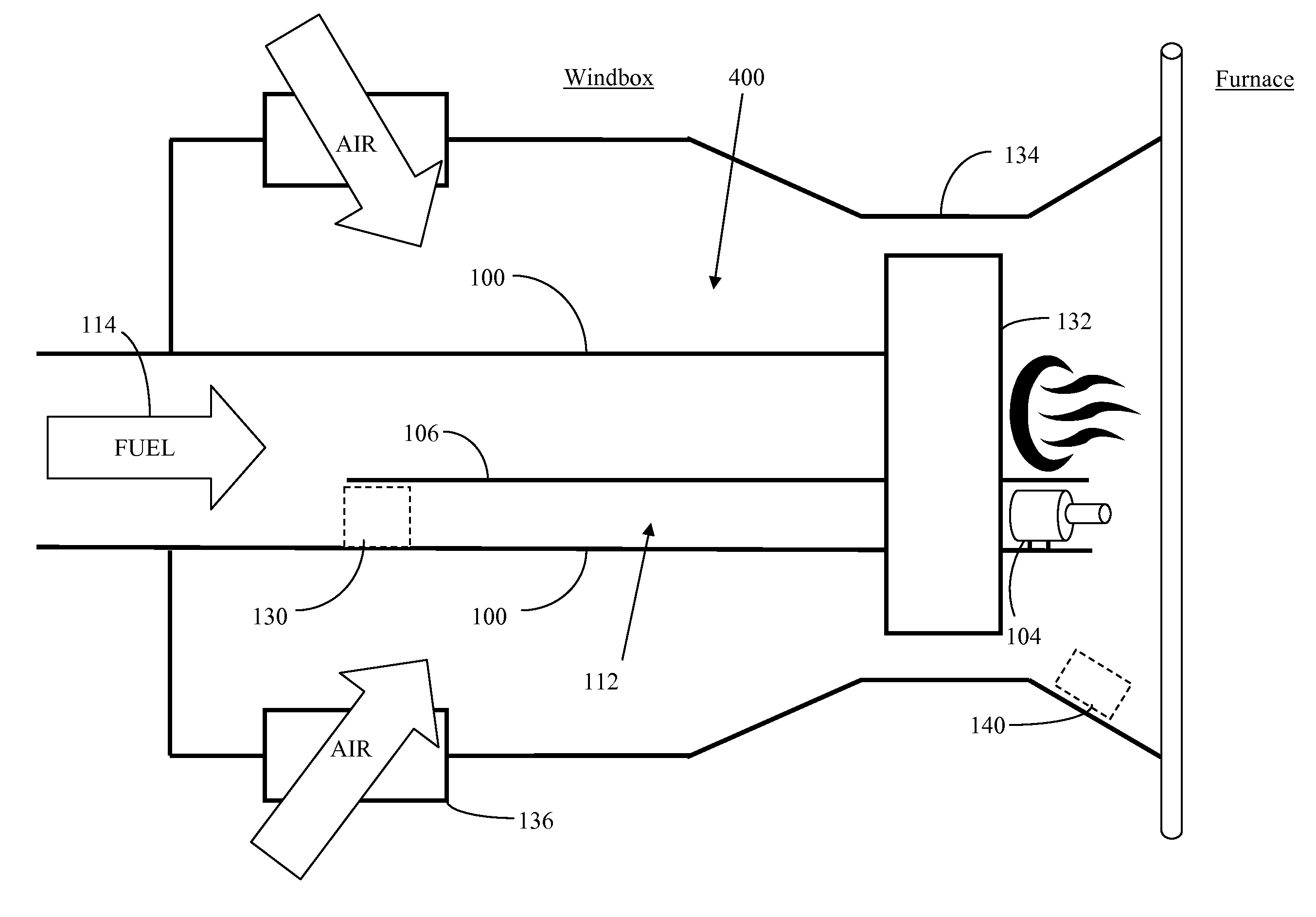
[0025]Large-scale combustion systems include utility power plants, paper& pulp mills, chemical plants, oil refineries, ethanol plants, marine vessels, and diesel engines, among others. Typically, utility & industrial boilers and transportation industries utilize steam generators ranging in size from 10 MW to 800 MW (50,000 to 5,500,000 lb / hr steam flow) and run on any number of different types of fuels, including coal, natural gas, fuel oil, refinery gas, and biofuel, although not limited thereto. Such systems require reliable ignition sources in order to maximize efficiency and to minimize risks associated with unintended explosions.

[0026]Typically, large-scale combustion systems utilize pilot ...


PUM


Abstract

A large-scale combustion system has a fuel line having a burner end, a burner at the burner end of the fuel line, a source of fuel flowing through the fuel line to the burner, a hot surface igniter adjacent to the fuel line, a flame holder disposed adjacent to the hot surface igniter, and a source of igniter combustion air. The hot surface igniter is activated to ignite the source of fuel, the ignited fuel leaving the burner, and the hot surface igniter is protected from a heat caused by the ignited fuel. A flame detector detects ignition of the source of fuel and in response to detection of ignition the hot surface igniter is deactivated.

Description

FIELD OF THE INVENTION[0001]The present teachings relate generally to large-scale combustion systems and, more particularly, to hot surface ignition devices in such systems.BACKGROUND OF THE INVENTION[0002]Large-scale combustion systems (e.g., utility & industrial boilers) use controlled combustion of fuel to provide a source of heat. A burner mixes fuel and oxygen together and, with the assistance of an ignition device, provides a platform for combustion. Controls may regulate the ignition device, fuel supply, air supply, and pressure. By ensuring efficient ignition and mixing of air and fuel as it enters the burner, combustion efficiency can be maximized while NOx emissions can be reduced.[0003]When incomplete combustion occurs, the energy of the fuel is not completely released as heat and the combustion efficiency is reduced. Inefficient ignition and improper control of flame stability and flame location, particularly during cold startup, process upsets, or turndown conditions, m...

Claims


Application Information

Patent Timeline
Patent Type & Authority Applications(United States)
IPC IPC(8): F23N5/20F23Q3/00F23Q7/06
CPCF23N5/20F23Q3/008F23Q7/06F23D2207/00F23D2208/10F23N2900/05005F23N2227/28F23N2229/00
Inventor SCHINDLER, EDMUND S.DALE, JOHN N.
Owner PEERLESS MFG CO
Why Eureka
Try Eureka