
MEMS device having a microphone structure, and method for the production thereof

a technology of a microphone and a diaphragm, which is applied in the direction of miconductor electrostatic transducers, loudspeakers, coatings, etc., can solve the problems of mechanical tension in the diaphragm structure, disadvantageous effect of the microphone, and known microphone devices, so as to reduce mechanical tension in the diaphragm and good acoustic sealing of the microphone structure

Active Publication Date: 2015-01-15
ROBERT BOSCH GMBH
View PDF28 Cites 30 Cited by
  • Summary
  • Abstract
  • Description
  • Claims
  • Application Information

AI Technical Summary

Benefits of technology

The present invention proposes measures to reduce mechanical tension in the microphone diaphragm, provide substrate-side overload protection, and achieve good acoustic sealing of the microphone structure. The microphone diaphragm is designed in a flexible beam form with a pan-shaped edge that overlaps the edge region of the through-opening in the base substrate. This edge region promotes acoustic sensitivity and forms an edge seal for the microphone structure. The edge region of the counter-element also forms an edge seal for the microphone diaphragm. The concentration of stress in the diaphragm structure can be reduced by selecting curved diaphragm edges and large curvature radii. The microphone diaphragm is made in a semiconductor layer with good mechanical properties. The signal acquisition takes place capacitively, and the counter-element is fixedly positioned and only the electrode on the microphone diaphragm is deflected as a result of sound. The counter-element is realized in a layer composite under tensile stress, made of at least one electrically insulating layer and at least one conductive layer. The electrically insulating layers have high specific resistance, mechanical tensile stress, and breaking strength to prevent short circuit of the microphone condenser system in case of overload situations.

Problems solved by technology

However, the known microphone device is also problematic in several ways.
Thus, the combination of the metallic diaphragm material with the dielectric material of the diaphragm suspension necessarily causes mechanical tensions in the diaphragm structure which have a disadvantageous effect on the microphone properties.
However, this works against the dismantling of mechanical tensions in the diaphragm structure.

Method used


Image

  • MEMS device having a microphone structure, and method for the production thereof
  • MEMS device having a microphone structure, and method for the production thereof
  • MEMS device having a microphone structure, and method for the production thereof

Examples


Embodiment Construction

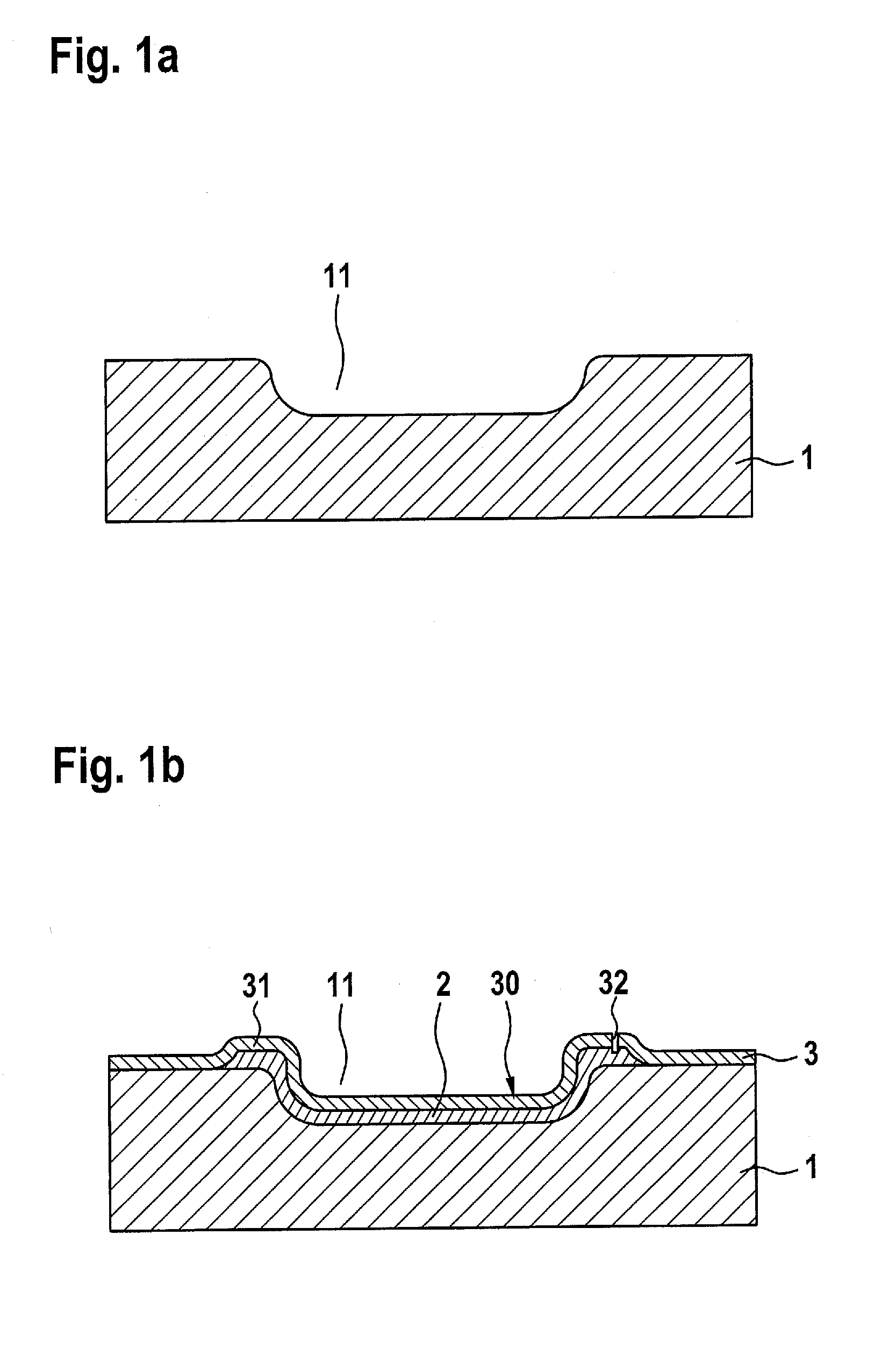
[0024]The starting point for the production of a MEMS device having a microphone structure of the type under consideration here is a base substrate 1. This can be for example a monocrystalline silicon substrate, as in the exemplary embodiment described here, or can also be an SOI wafer or some other semiconductor bearer. Figure la shows base substrate 1 after a recess 11 has been made in the substrate surface for the realization of the microphone diaphragm. The depth and shape of this recess 11 determine the pan shape of the microphone diaphragm. In order to avoid mechanical stresses in the diaphragm structure, here rounded-off contours have been chosen for the microphone diaphragm and, correspondingly, for recess 11. In principle, recess 11 can be produced using any structuring method. In order to obtain edges that are as rounded off as possible, in the example shown here the silicon in the region of recess 11 that is to be produced is first etched in porous fashion and then select...


PUM

PropertyMeasurementUnit
Radiusaaaaaaaaaa
Flexibilityaaaaaaaaaa
Tensile stressaaaaaaaaaa

Abstract

A microphone structure of an MEMS device has a layer construction including: a base substrate; a deflectable microphone diaphragm at least partly spanning a through-opening in the substrate; a deflectable electrode of a microphone condenser system; a stationary counter-element having ventilation openings situated in the layer construction over the microphone diaphragm and acting as a bearer for a stationary electrode of the microphone condenser system. The diaphragm is bonded into the layer construction on the substrate via a flexible beam. The otherwise free edge region of the diaphragm is curved in a pan shape, so that it extends both vertically and also in some regions laterally beyond the edge region of the through-opening, and the edge region of the through-opening forms a lower stop for the diaphragm movement.

Description

BACKGROUND OF THE INVENTION[0001]1. Field of the Invention[0002]The present invention relates to a MEMS device having a microphone structure, and to a method for the production thereof.[0003]2. Description of the Related Art[0004]The microphone structure is realized in a layer construction on a base substrate; it includes a deflectable microphone diaphragm and a stationary counter-element having ventilation openings. The microphone diaphragm spans a through-opening in the base substrate, the mid-region of the microphone diaphragm being essentially plane-parallel to the substrate plane and, in the rest state, being situated inside the through-opening in the base substrate. The microphone diaphragm is provided with at least one deflectable electrode of a microphone condenser system. The stationary counter-element is configured in a layer construction over the microphone diaphragm, and acts as bearer for at least one stationary electrode of the microphone condenser system.[0005]Such a ...

Claims


Application Information

Patent Timeline
IPC IPC(8): B81B3/00B81C1/00
CPCB81B3/0072B81B2203/0127B81C1/00158B81B2201/0264B81B3/0059B81B2201/0257B81C1/00666H04R19/005H04R2201/003
Inventor SCHELLING, CHRISTOPHSINGER, STEFANZOELLIN, JOCHEN
Owner ROBERT BOSCH GMBH
Learn More