
Interface device for video cameras

a technology of video cameras and interface devices, which is applied in the direction of closed-circuit television systems, electrical equipment, television systems, etc., can solve the problems of future extension of the plant, inability to meet the needs of the customer,

Inactive Publication Date: 2015-01-15
VIDEOTEC SPA
View PDF2 Cites 5 Cited by
  • Summary
  • Abstract
  • Description
  • Claims
  • Application Information

AI Technical Summary

Benefits of technology

The present invention provides an interface device for video cameras that combines the benefits of digital dome cameras and analog pan and tilt systems while offering maximum flexibility of use and installation. The device can function as a client or server to download or send data from the camera in real-time to a control terminal or video control system. The output data streams include audio, video, and metadata all transferred in a single stream. A hardware and software switch can be used to reduce the necessary hardware and software while an electronic circuit can be implemented to perform the sorting and switching of packets. The interface device acts as a firewall to protect the camera against network attacks.

Problems solved by technology

Unfortunately, the passage from these analog systems to digital systems also provided the rising of some incompatibilities with the typical architecture of the conventional systems.
Dome cameras, however, although they are very simple and therefore of immediate use, they are systems with well precise constructional details and therefore, they do not have such flexibility in the installation that is the main characteristic of systems that bear conventional housings or pan and tilt units.
Encoders often have been certified for the installation in indoor environments, therefore the system has to provide an analog wiring anyway, which therefore is a limit for the future extension of the plant.
If they are certified for being used in outdoor environments, it is necessary to install a junction box placed close to the pan and tilt unit; this installation cannot be always of easy implementation.
Moreover these devices do not allow a video camera to be controlled as a dome camera, namely by means of commands sent through the IP network, since the connection with the camera itself is of the analog type by means of a coaxial cable only for receiving the video streaming that, once coded, is directed on the IP network.
In practice the encoder devices use the network for sending commands only to the pan and tilt unit and for receiving streaming of video data, but they are not able to send commands to the video camera for controlling the quality of the compressed video as it occurs in the case of a dome camera.
The drawback of such solution mainly is the fact that the control of the pan and tilt unit is related to the support of a protocol in common to the video camera and the pan and tilt unit.
Once such common protocol is defined, then there is a limit in the commands that can be sent, since not all the commands of the pan and tilt unit will be anyway supported by the video camera resulting in the pan and tilt unit operating only with a subset of its functionalities.
For instance, it is possible to move the pan and tilt unit, but it is not possible to control the wiper or any other equipment fitting of the pan and tilt unit or of the housing, since the protocol managing such devices cannot be the same that manages the video camera.

Method used


Image

  • Interface device for video cameras
  • Interface device for video cameras
  • Interface device for video cameras

Examples


Embodiment Construction

[0048]Coherently with the terminology of the sector, in the present description below, by “pan and tilt unit” we refer to a unit for the positioning of a device, particularly a video camera, which, provided with electronically controllable mechanical means, allows a remote user to control and change at least the position (pan and tilt) of the device fitted thereon.

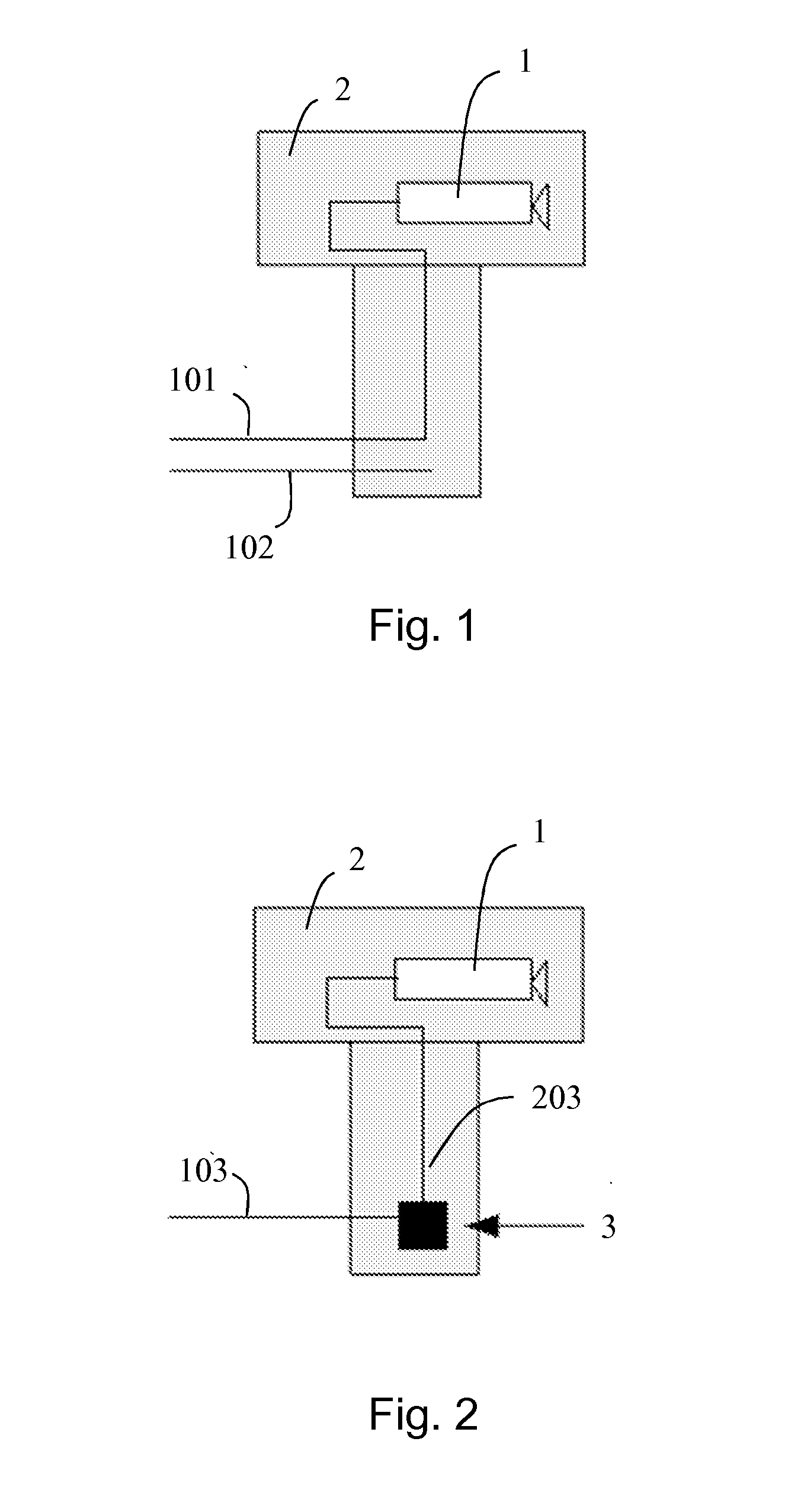
[0049]FIG. 1 schematically shows a pan and tilt unit / video camera combination of the analog type. Such combination is an example of a video surveillance station that can be used for monitoring an environment.

[0050]The video camera 1, mounted on the top of the pan and tilt unit, has an output on a coaxial cable 101 to which a monitor or a video recorder can be connected (not shown in the figure). The pan and tilt unit 2 in turn has an input represented by the cable denoted by reference 102. In practice it is a copper twisted pair cable on which the telemetric commands sent by a keypad (not shown in the figure) serially pass...


PUM


Abstract

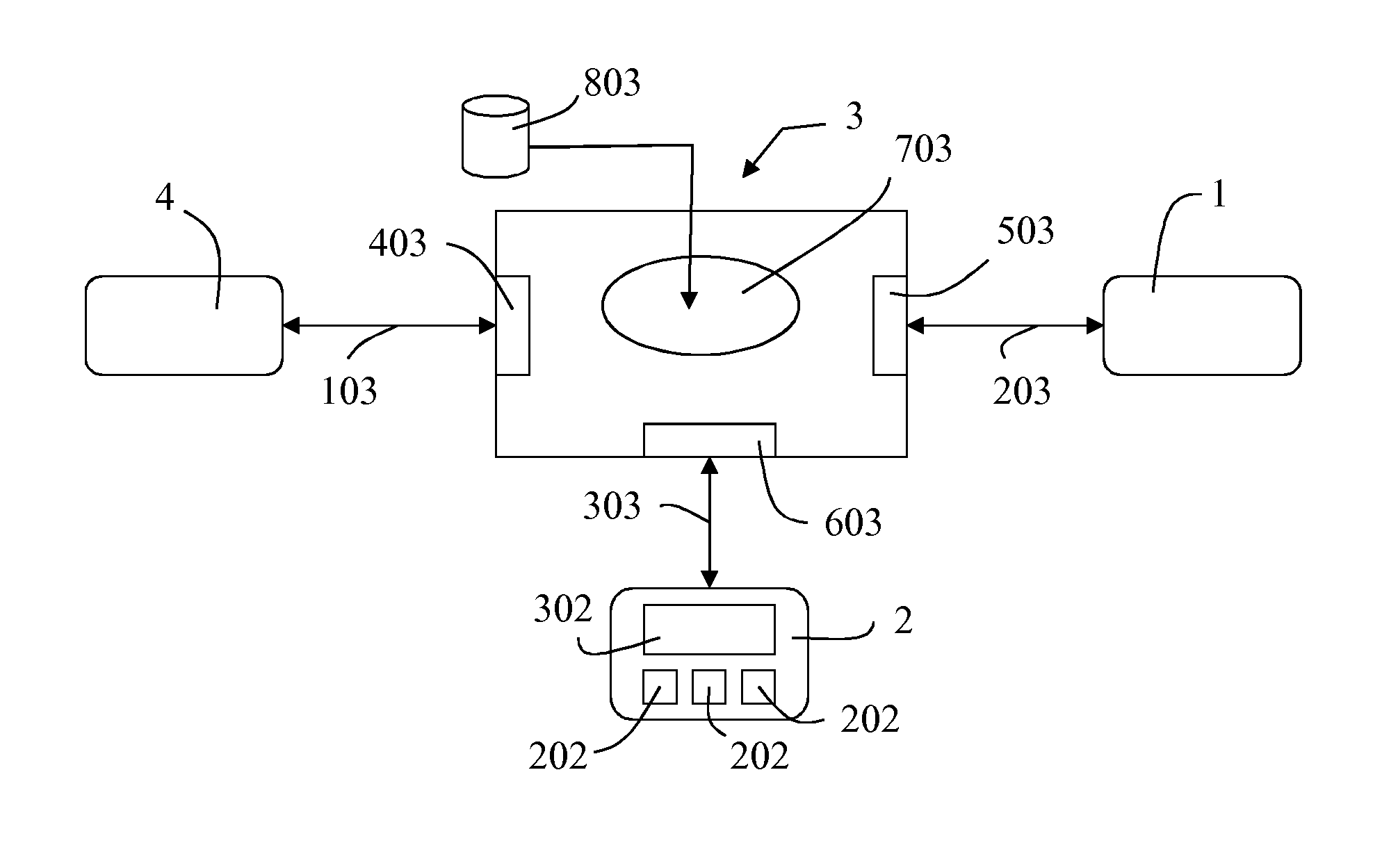
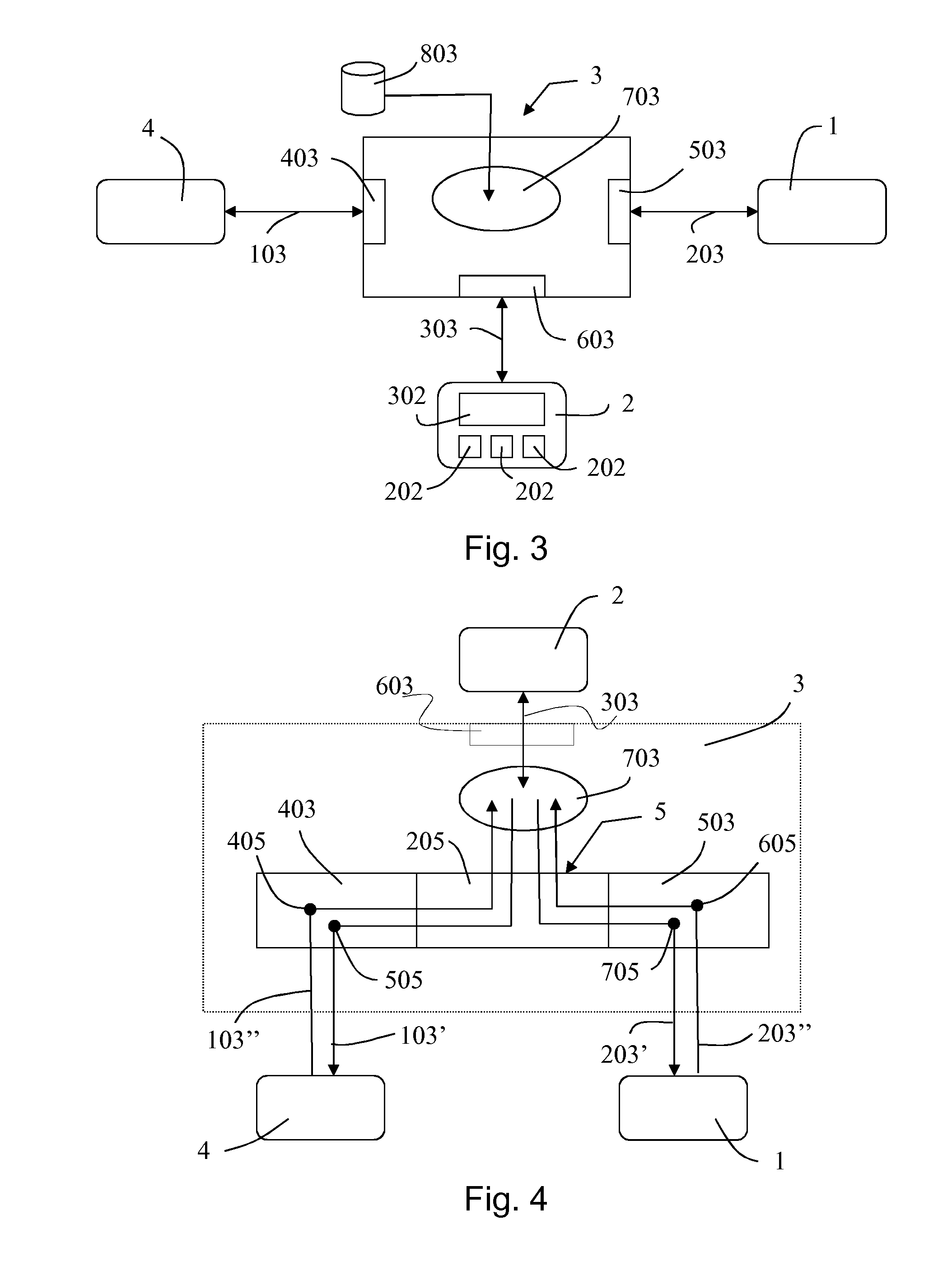
The present invention relates to an interface device (3) for video surveillance stations of the type comprising a video camera (1) and a positioning unit (2) for the video camera (1). The device (3) comprises a first port (403) for the connection to a remote terminal (4), a second port (503) for the connection to a video camera (1), a third port (603) for the connection to a positioning unit (2) for the video camera (1), and a microprocessor circuit (703) operatively connected to said three ports for transferring the commands received through the first port (403) to the second port (503) and / or to the third port (603). The microprocessor circuit (703) communicates with the video camera (1) and with the remote terminal (4) through two networks (103, 203) separated at physical or logical level, such that only the microprocessor circuit (703) is able to send the data received from a remote terminal (4) to a video camera (1) or to a positioning unit (2) and vice versa, while a remote terminal (4) is not able to communicate with a video camera (1) or with the a positioning unit (2).

Description

TECHNICAL FIELD[0001]The invention relates to an interface device for video surveillance stations of the type comprising a video camera and a local control system for the station. The local control system comprises a control unit that controls a plurality of devices and actuators such as pan and tilt units, housings and relevant equipment fittings.PRIOR ART[0002]Pan and tilt units, that is positioning systems for video cameras for CCTV applications, are devices remotely controlled by interfaces well-established over the years: the coaxial cable for transporting the video from the video camera (mounted on the pan and tilt unit) to a remote video surveillance centre, and a serial line for exchanging telemetry commands for moving the pan and tilt unit. The serial line can use the copper twisted pair cable as the transmission means or it can be transmitted on the same coaxial cable by means of suitable modulation techniques.[0003]Leaving out the mechanical features, such as for example ...

Claims


Application Information

Patent Timeline
Patent Type & Authority Applications(United States)
IPC IPC(8): H04N7/18
CPCH04N7/181
Inventor CAMPANA, OTTAVIO
Owner VIDEOTEC SPA
Learn More