
Redox flow battery and cell frame

a cell frame and redox flow technology, applied in the direction of electrolyte stream management, indirect fuel cells, sustainable manufacturing/processing, etc., can solve the problem of significant environmental contamination caused by emitted co2 gas, limited use of new renewable energy, and inability to completely prevent electrolyte leakage, etc., to achieve the effect of preventing electrolyte leakag

Inactive Publication Date: 2015-01-15
OCI
View PDF6 Cites 9 Cited by
  • Summary
  • Abstract
  • Description
  • Claims
  • Application Information

AI Technical Summary

Benefits of technology

The present invention is about a new type of redox flow battery that prevents electrolyte leakage and has a high efficiency and reliability. It is made by integrating a protection plate and a unit frame, which surrounds the electrolyte channel and bipolar plate. The thickness of the protection plate is the same as the bipolar plate, and they are both made of insulation material. This design prevents the leakage of the electrolyte and ensures the stability of the battery. Additionally, it prevents the decrease of the output from the battery and simplifies the coupling process.

Problems solved by technology

In most of the power supply systems, a thermal power generation is prominent, but in thermal power generation, a large amount of CO2 gas is emitted by using fossil fuel, and an environmental contamination problem due to the emitted CO2 gas is significantly serious.
However, since the new renewable energy is significantly affected by natural environments, an output variation width depending on time is significantly large, such that there is a limitation in using the new renewable energy.
In this case, since the processing of the cell frame is complicated, and the protection plate is not completely integrated with the cell frame, the protection plate may be separated due to a durability problem, such that leakage of the electrolyte may not be completely prevented.

Method used

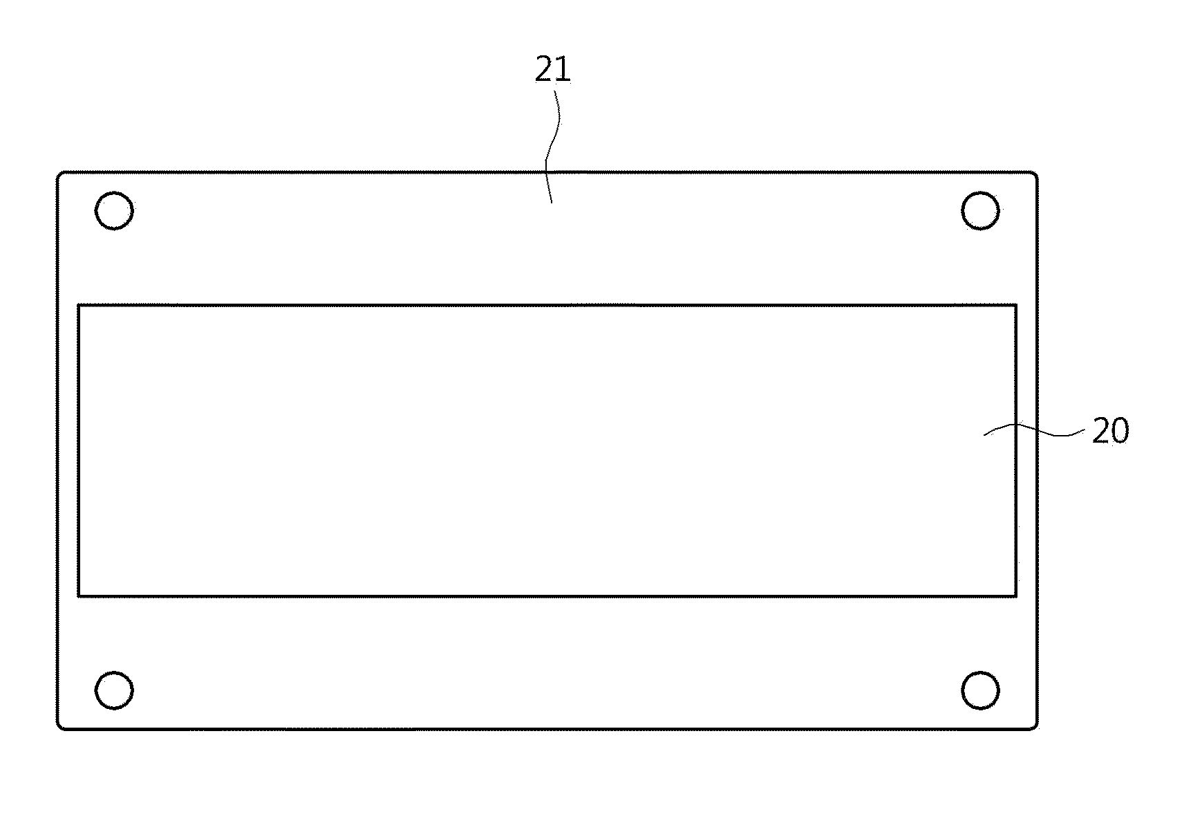
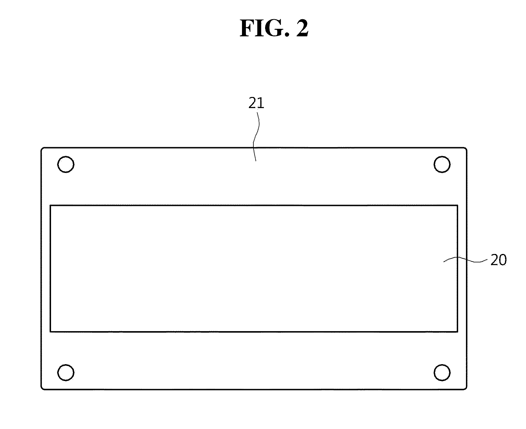

Image

  • Redox flow battery and cell frame
  • Redox flow battery and cell frame
  • Redox flow battery and cell frame

Examples


Embodiment Construction

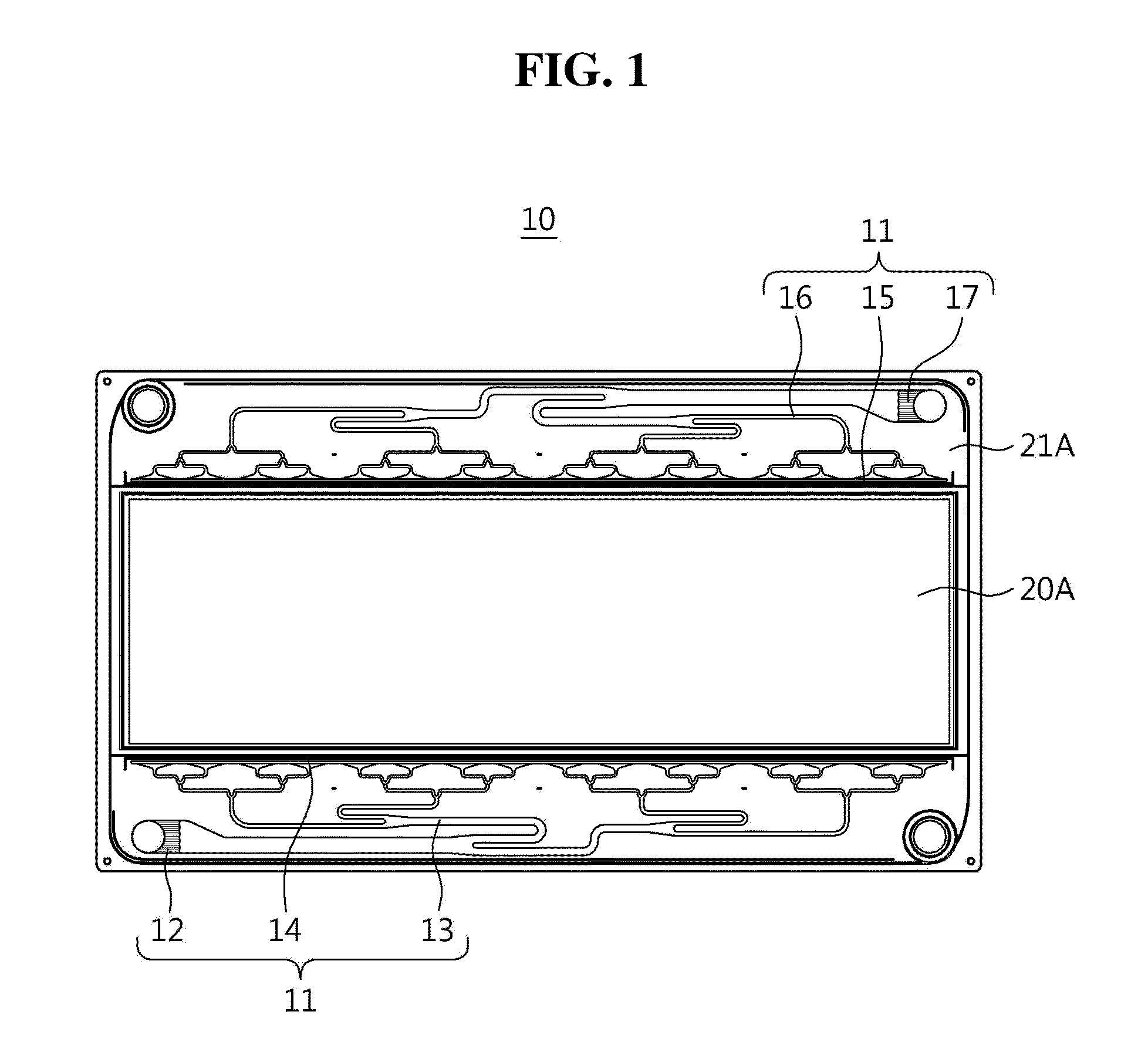
[0026]FIG. 1 is a planar view of a unit frame 10 configuring a cell frame. Referring to FIG. 1, an electrolyte channel 11 is formed at upper and lower end portions of a contact region the unit frame 10.

[0027]The electrolyte channel 11 is composed of an electrolyte inlet part 12, a first distribution channel 13, a first penetration channel 14, a second penetration channel 15, a second distribution channel 16, and an electrolyte outlet part 17.

[0028]An electrolyte supplied from a tank is introduced in the electrolyte inlet part 12 and uniformly distributed through the first distribution channel 13. The distributed electrolyte is supplied to a front surface of a bipolar plate through the first penetration channel 14. Then, the electrolyte is released from the front surface of the bipolar plate 20 to the second distribution channel 16 positioned at an inner portion of the cell frame through the second penetration channel 15, and the electrolyte distributed through the second distributio...


PUM

PropertyMeasurementUnit
thicknessesaaaaaaaaaa
acid resistantaaaaaaaaaa
areaaaaaaaaaaa

Abstract

Disclosed herein are a redox flow battery and a cell frame. In a cell frame of a redox flow battery, the cell frame comprising: a pair of unit frames adhered to each other; a protection plate shared by the unit frames, wherein each unit frame includes an electrolyte channel formed on a contact region of the unit frame with the protection plate; and a bipolar plate on which an electrolyte flows, wherein the electrolyte is supplied through the electrolyte channel. The cell frame has an integration type structure in which the protection plate is positioned in the cell frame, such that leakage of the electrolyte may be effectively prevented.

Description

CROSS REFERENCE TO RELATED APPLICATION[0001]This application claims the benefit of Korean Patent Application NO. 10-2013-0082169, filed on Jul. 12, 2013, entitled “Redox Flow Battery and Cell Frame” and Korean Patent Application NO. 10-2013-0082065, filed on Jul. 12, 2013, entitled “Cell Frame for Improved Flow Distributing and Redox Flow Battery Having the Same”, which are hereby incorporated by reference in their entirety into this application.BACKGROUND OF THE INVENTION[0002]1. Technical Field[0003]The present invention relates to a redox flow battery and a cell frame, and more particularly, to a redox flow battery and a cell frame capable of effectively preventing leakage of an electrolyte in the cell frame by including an electrolyte channel protection plate between a pair of unit frames adhered to each other, and having excellent durability.[0004]2. Description of the Related Art[0005]Recently, a global effort to decrease greenhouse gas has been made due to environmental conta...

Claims


Application Information

Patent Timeline
Patent Type & Authority Applications(United States)
IPC IPC(8): H01M8/02H01M8/20H01M8/18
CPCH01M8/20H01M8/0258H01M8/188H01M8/2455H01M8/006H01M8/04276Y02E60/50Y02P70/50Y02E60/10H01M10/38
Inventor KIM, SOO-WHANUM, MYUNG-SUPKIM, TAE-YOONHA, TAE-JUNGBANG, YOO-KYUNG
Owner OCI
Learn More