This helps you quickly interpret patents by identifying the three key elements:
Problems solved by technology
Method used
Benefits of technology
[0018]In so doing, there are fewer instances in which, due to the maximum motor travel torque having been set to a large value, the maximum torque of which the motor is capable of outputting is output to meet the required engine-starting torque when an engine start demand occurs, and the load on the inverter can be reduced. Additionally,
Problems solved by technology
When a demand to start the engine is issued in such a case, the motor will output the maximum torque it is capable of outputting in order to meet the required engine-starting torque, which places a high load on the inverter which controls the motor, posing a risk of leading to component failure.
Furthermore, when motor travel is sustained despite the torque demand information reaching a large value, power from the battery is consumed to an excessive extent, the remaining battery capacity becomes low, and it is con
Method used
Image
Click on the blue label to locate the original text in one second.
Reading with bidirectional positioning of images and text.
Examples
embodiment 1
[0048]The configuration shall be described first.
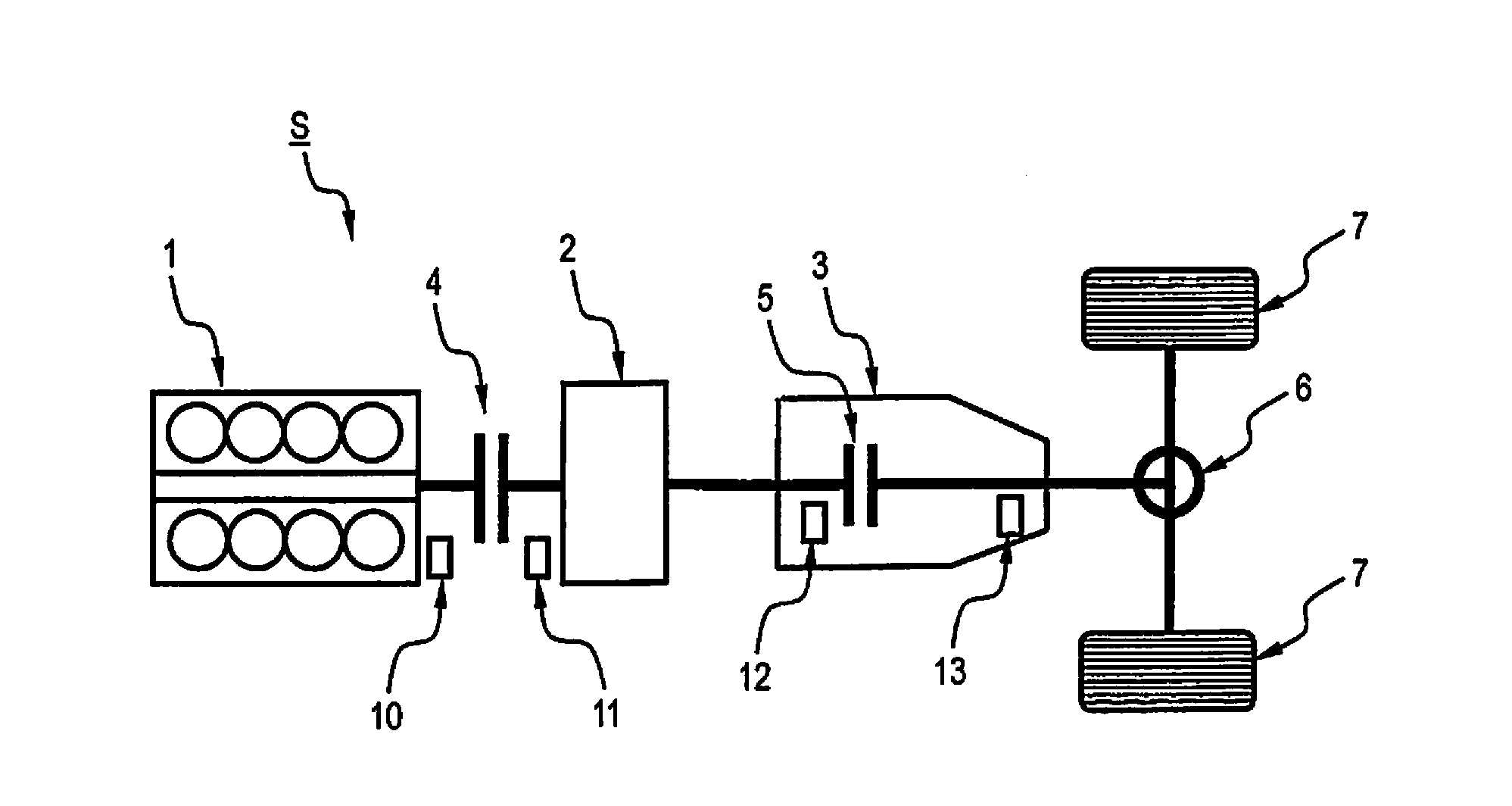
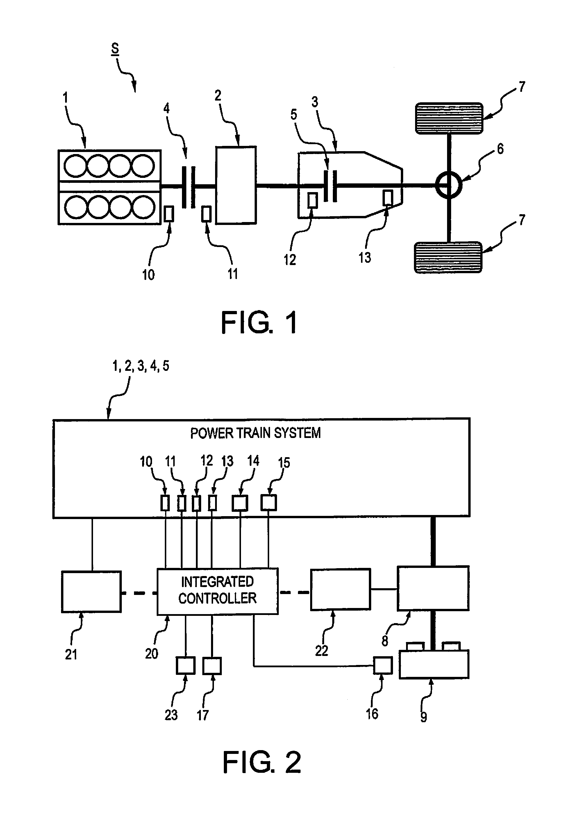
[0049]FIG. 1 is a powertrain system configuration diagram showing a powertrain of a hybrid vehicle in which the control device for a hybrid vehicle according a first embodiment is implemented. The following description of the powertrain is based on FIG. 1.
[0050]As shown in FIG. 1, the powertrain system of the hybrid vehicle S of the first embodiment is equipped with an engine 1, a motor-generator 2 (motor), an automatic transmission 3, a first clutch (mode switching means) 4, a second clutch 5, a differential gear 6, and tires (drive wheels) 7, 7.
[0051]The hybrid vehicle S of the first embodiment has a powertrain system configuration equipped with the engine and the one motor / two clutches, and has as driving modes an “HEV mode” in which the first clutch 4 is engaged, an “EV mode” in which the first clutch 4 is released, and a “WSC mode” in which the second clutch 5 is slip-engaged during travel.
[0052]The engine 1 is linked at the outp...
embodiment 2
[0251]A second embodiment relates to an example in which an engine-start line (intent-to-accelerate start line) is set according to intent to accelerate, and the smaller of an expansion start line and the intent-to-accelerate start line is selected as the final engine-start line.
[0252]FIG. 21 is a flowchart showing the flow of an engine-start condition setting process executed by the integrated controller of a second embodiment. The steps of FIG. 21 are described below.
[0253]In Step S1A, the vehicle speed VSP, the accelerator position APO, and the state of battery charge SOC are detected, and the routine advances to Step S2.
[0254]Here, the vehicle speed VSP is calculated through multiplication of a preset proportionality coefficient, by the number of rotations of the output shaft of the automatic transmission 3 detected by the AT output shaft rotation sensor 13. The accelerator position APO is detected by the accelerator position sensor 17. The state of battery charge SOC is detecte...
PUM
Abstract
A control device for a hybrid vehicle is configured to enter a driving mode in which a preset engine-start condition is met, and is configured to enter electric vehicle mode when a preset engine-stop condition is met, and includes an engine-start-condition-controlling device which, during travel in the electric vehicle mode, in the event that an electric vehicle travel zone expansion condition that has been set on the basis of vehicle speed VSP and torque demand information reflective of demand by the driver, and that expands the travel zone in the electric vehicle mode, is met, changes the engine-start condition from a baseline start condition, to an expansion engine-start condition for expanding the travel zone in the electric vehicle mode, doing so for the duration of a prescribed time thereafter.
Description
CROSS-REFERENCE TO RELATED APPLICATIONS[0001]This application is a U.S. National stage application of International Application No. PCT / JP2013 / 056127, filed Mar. 6, 2013, which claims priority to Japanese Patent Application No. 2012-056034 filed in Japan on Mar. 13, 2012, the contents of each of which are hereby incorporated herein by reference.BACKGROUND[0002]1. Field of the Invention[0003]The present invention relates to a control device for a hybrid vehicle, whereby the engine-start condition for initiating mode transition from electric vehicle mode to hybrid vehicle mode can be made to differ depending on the condition.[0004]2. Background Information[0005]In the prior art, when torque demand information reflective of demand by the driver exceeds an engine start line that was set according to vehicle speed, the engine is started to bring about mode transition from electric vehicle mode to hybrid vehicle mode. That is, a zone for travel in electric vehicle mode (hereinafter termed...
Claims
Application Information
Patent Timeline
Application Date:The date an application was filed.
Publication Date:The date a patent or application was officially published.
First Publication Date:The earliest publication date of a patent with the same application number.
Issue Date:Publication date of the patent grant document.
PCT Entry Date:The Entry date of PCT National Phase.
Estimated Expiry Date:The statutory expiry date of a patent right according to the Patent Law, and it is the longest term of protection that the patent right can achieve without the termination of the patent right due to other reasons(Term extension factor has been taken into account ).
Invalid Date:Actual expiry date is based on effective date or publication date of legal transaction data of invalid patent.