Conveying device and process for operating the same

a technology of conveyor system and inclination angle, which is applied in the direction of conveyor parts, loading/unloading, transportation and packaging, etc., can solve the problems of reducing the mobility and versatility of a tripper conveyor system, limiting the mobility and versatility of the system, and not being able to achieve the reduction of friction at higher inclination angles

Inactive Publication Date: 2015-01-22
F L SMIDTH & CO AS
View PDF4 Cites 9 Cited by
  • Summary
  • Abstract
  • Description
  • Claims
  • Application Information

AI Technical Summary

Benefits of technology

[0010]It is another object of the invention to improve the efficiency of current mobile conveying systems and processes by providing a “direct engagement” between the tripper and conveyor without the need for cables and complex pulley systems.
[0011]Yet another object of the invention is to prevent or minimize machine downtime, capital costs, and maintenance costs.
[0012]Another object of the invention is to maximize safety and control of tripper conveyor systems.
[0013]Another object of the invention is to provide a tripper drive system which costs less, has a smaller footprint, is more versatile, and is less complex than conventional tripper drive systems.
[0014]Another object of the invention is to provide a tripper drive system which is configured to operate at higher inclination angles than conventional tripper drive systems, without requiring downtime and capital expenditure for lengthening, shortening, or replacing cables.
[0022]In some embodiments, the conveyor is configured to safely operate at positive and negative inclination angles between approximately 0 and 14 degrees with respect to horizontal. The at least one elongated transmission member comprises a plurality of teeth and valleys disposed between said teeth which may be configured to mesh with threads of a worm, or teeth of a cogwheel or lantern pinion. Swept chamfers may be provided to the at least one elongated transmission member in order to shed material and prevent clogging

Problems solved by technology

Capstan drives typically rely on cable tension and friction between the cable and a complicated system of motor-driven sheaves to move the tripper.
Problems associated with the abovementioned conventional tripper drives are numerous.
Particularly in adverse weather conditions or high dust environments inherent to mining operations, higher inclination angles might not be possible to do decreased friction between the conveyor wheel rails 816 and trolley wheels.
Such limits reduce the mobility and versatility of a tripper conveyor system.
Moreover, when using standard induction drives, if the tripper brakes fail, the tripper may not stop when in a parked position, causing a potential hazardous “sliding” situation.
Lastly, delays in starting, stopping, and reversing movement of the tripper as well as “wheel slip”, “sliding”, or “spinning out” may be experienced as a result of constantly changing coefficients of friction between the drive wheels and wheel rail 816.
Moreover, while capstan drive systems afford greater operational inclination angles than standard induction drives, they are expensive and require expensive, specially-designed, cables which need to be replaced approximately every six months.
The cables are constantly exposed to high abrasion, rely on a coefficient of friction that is dependent on cable tension, attract dirt when greased, and tend to stretch under heavy loads thereby providing a delayed or indiscernible starting and stopping response when moving or reversing the tripper.
Moreover, while cable lengths can be shortened, they cannot be elongated without changing the uniformity of cable properties.
Therefore, capstan drives lack total mobility and versatility because conveyors must be kept the same predetermined length for the life of the cable, unless the tripper conveyor system is shut down temporarily for cable maintenance, adjustment, or replacement.
Additionally, when it comes to “retrofitting” a tripper for use in steeper grades and rough terrain, a capstan upgrade is not typically a good option, since conveyor frames for use with capstan drives are typically initially made wider to accommodate and protect cables and also to allow some small misalignment between multiple conveyor sections without significant penalty (e.g., cable abrasion).
Therefore, especially in instances of significant terrain or inadvertent movement of conveyor frame sections, relative angles between hinged conveyor frame sections can become so severe that the cable can become slack or even severed between the wheels and wheel rail 816.
For example, in some instances, multiple conveyor frame sections may form a curved conveyor profile, wherein the cable is taught and follows a straight cable path or the cable is slack and meandering over the rail which leads to wear.
Such instances may pose great safety concerns for operators and increased risks to investors regarding unscheduled downtime for repairs and unexpected capital / maintenance costs.
Moreover, if a cable fails while under tension, it can become an extremely dangerous moving object for nearby operators.

Method used


Image

  • Conveying device and process for operating the same
  • Conveying device and process for operating the same
  • Conveying device and process for operating the same

Examples


Embodiment Construction

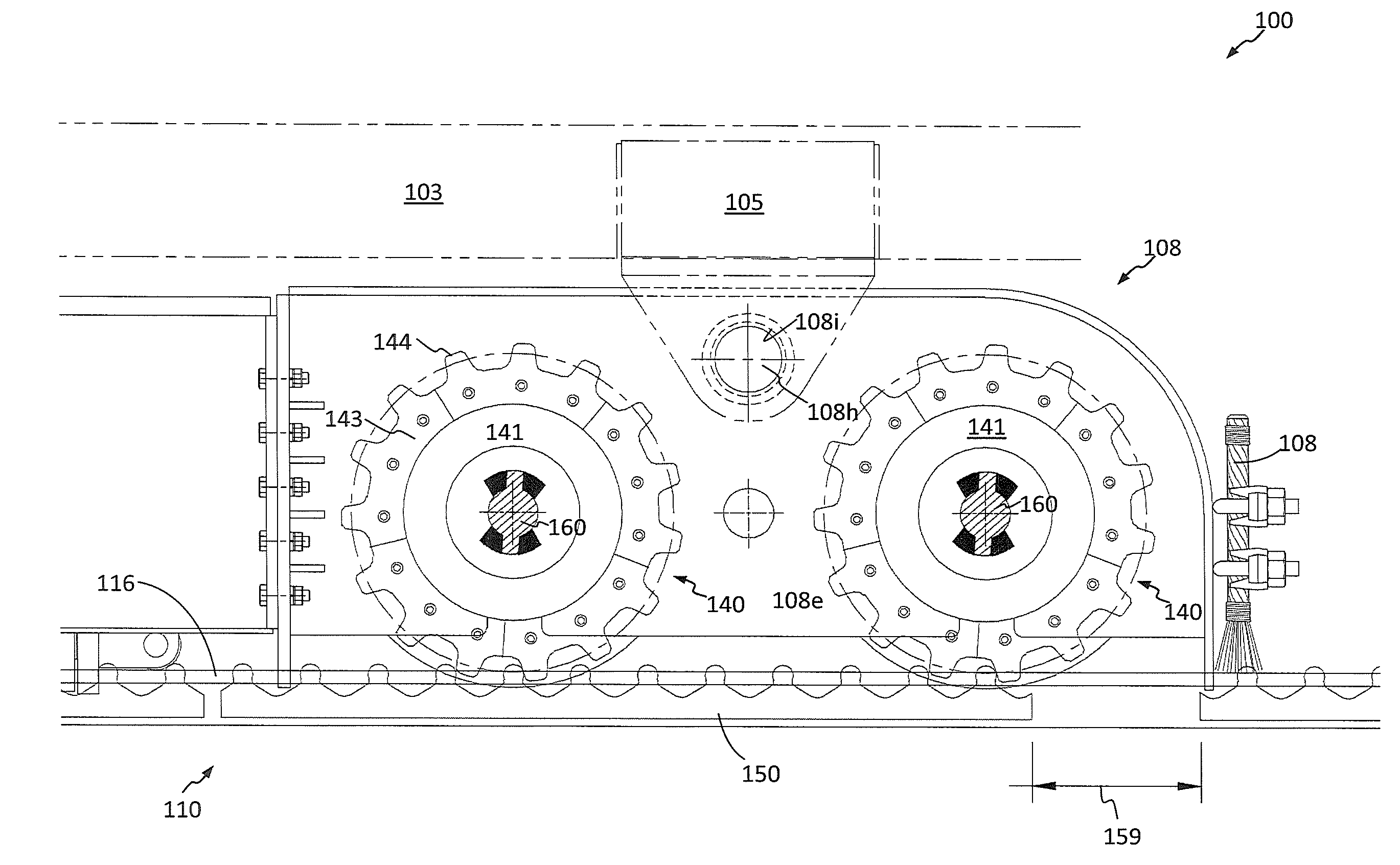
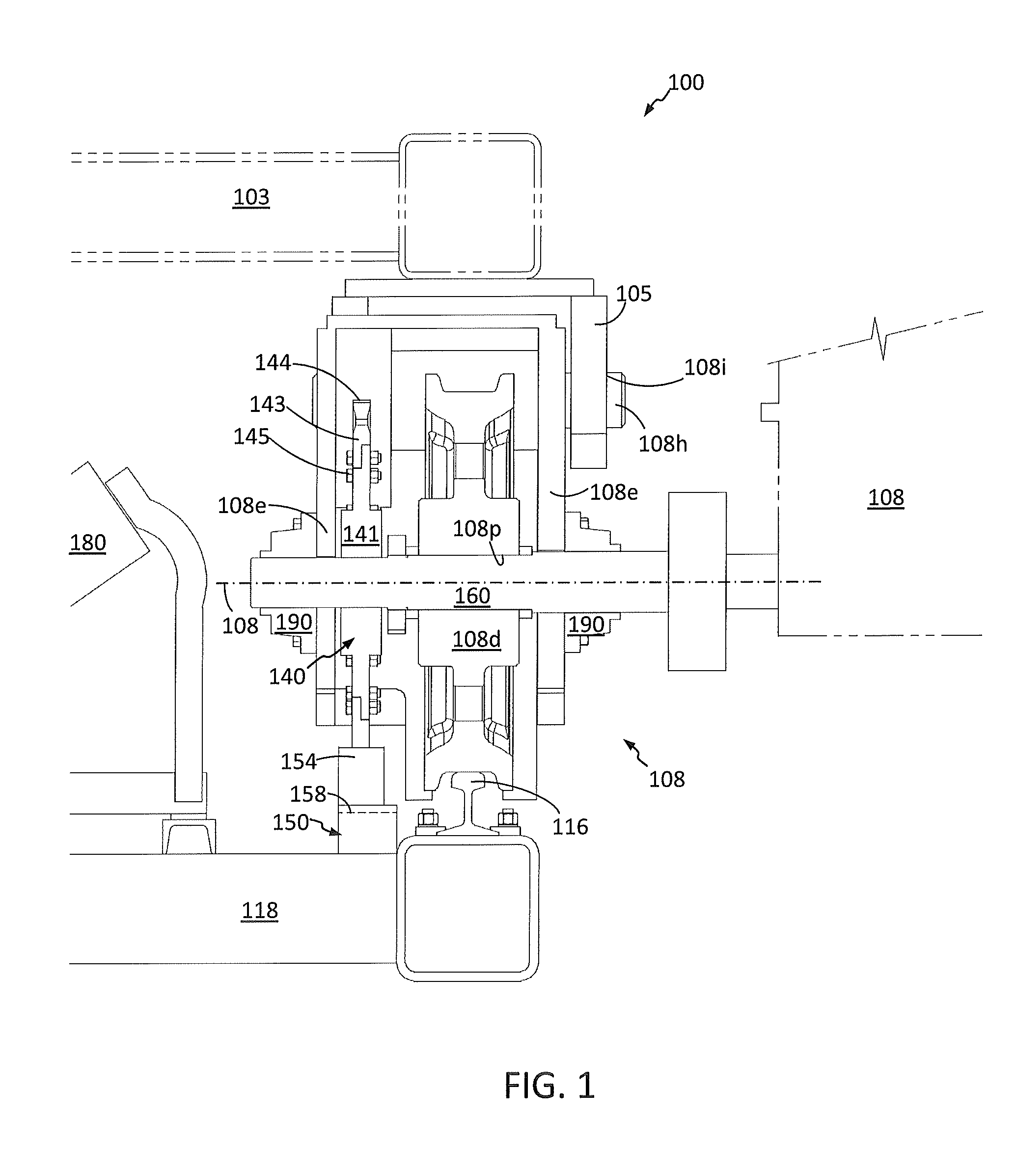
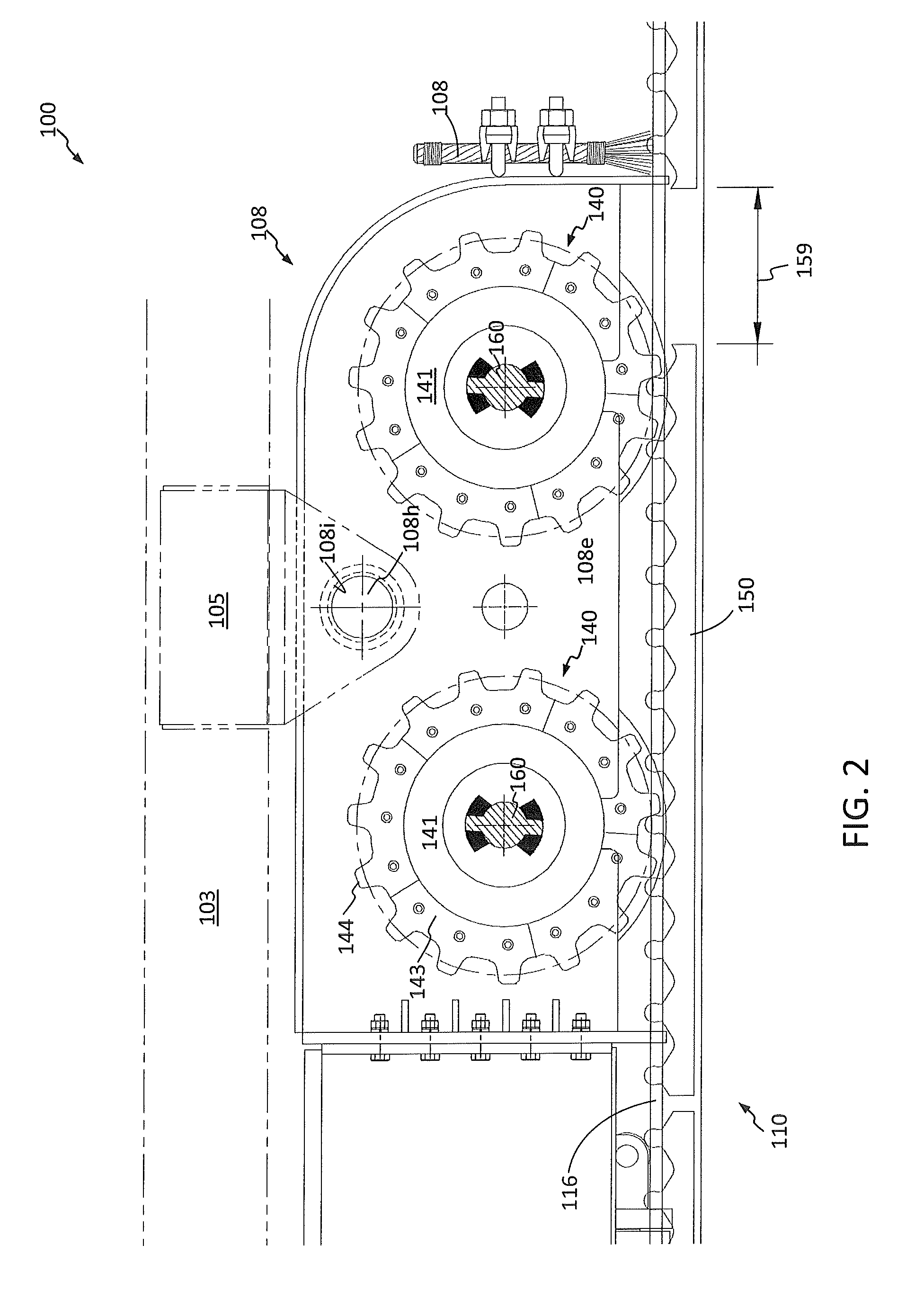
[0045]FIGS. 1-8 show a direct engagement drive system 108 for a tripper conveyor system according to some embodiments. A tripper 100 configured to rest on a conveyor 110 comprises a tripper frame 103 and feet 105, to which one or more drive systems 108 are attached. Multiple drive systems 108 may be provided to each foot 105. For example, as shown, each foot 105 may comprise two drive systems 108. Depending on which direction the tripper 100 is traveling, one of the two drive systems 108 serves as a lead drive system and the other of the two drive systems 108 serves as a follow drive system. The drive systems 108 are secured to a mount 108e which may be pivotally attached to each foot 105 by way of a joint 108h and / or a bushing 108i. The mount 108e may completely encase portions of each drive system 108 to protect components of the drive system 108 from dust and dirt ingress. For example, in some embodiments, such as the one shown, mount 108e may comprise a wheel box constructed of ...


PUM


Abstract

A direct engagement drive system [108] for a tripper conveyor system is disclosed. The drive system [108] comprises lead [140′] and follow [140″] cogwheels, each driven by a programmable logic controller [108q] and variable frequency drive-controlled electric motor [108a]. The torque applied to each of the lead [140] and follow [140] cogwheels varies as a function of loading experienced by the cogwheels [140] and as a function of the location of the cogwheels [140] relative to a gap [159] or other discontinuity in a cog rail [150] provided on a conveyor [110]. A process for moving a tripper [100] along a conveyor [110] is also disclosed. Other mobile conveying device such as mobile hoppers, maintenance vehicles, stacking machines, conveying devices, or cranes may employ the drive systems [108] shown and described.

Description

BACKGROUND OF THE INVENTION[0001]This invention relates to conveying equipment and more particularly to tripper conveyor systems used, for instance, in the mining, aggregate, agriculture, cement, waste management, and construction industries.[0002]A tripper is a type of industrial conveyor typically used in construction, mining, and other large-scale earth-moving businesses. For example, trippers may be used in conjunction with overland conveyor systems for mobile stacking of leach pads and storage piles. Such trippers uniformly spread mined material at variable heights over a predetermined area, facilitating leaching processes. Also known as a “tiered conveyor” or a “stepped conveyor”, a tripper provides flexibility within mobile materials handling systems as it rides on rails provided on a conveyor frame and travels forward or backward along the conveyor as needed. This allows the tripper conveyor system to load material onto a selected loading area of a transportation vessel or s...

Claims


Application Information

Patent Timeline
Patent Type & Authority Applications(United States)
IPC IPC(8): B65G23/04B65G15/00
CPCB65G47/945B65G15/00B65G23/04B65G41/02B65G65/28Y02P70/10
Inventor HANKS, JASON LESLIEMARVIN, ANDREW THADWADSWORTH, BRUCE EDDWARD
Owner F L SMIDTH & CO AS
Why Eureka
Try Eureka