Lens driving device and method of manufacturing the same

a driving device and lens technology, applied in the direction of mountings, dynamo-electric machines, instruments, etc., can solve the problems of inability to control easily, negatively affecting the anti-vibration effect and image quality, and achieve the effect of suppressing the first-order resonance peak and increasing the manufacturing yield ra

Active Publication Date: 2015-01-22
TDK TAIWAN
View PDF4 Cites 40 Cited by
  • Summary
  • Abstract
  • Description
  • Claims
  • Application Information

AI Technical Summary

Benefits of technology

[0015]The lens driving device and the method of manufacturing the same of the present invention are characterized in that an assembly including the plurality of magnets and the lens can be prevented from a yawing res

Problems solved by technology

In another aspect, according to the structure of the aforementioned conventional device, the peak of the first-order resonance of the coil plate 9, th

Method used


Image

  • Lens driving device and method of manufacturing the same
  • Lens driving device and method of manufacturing the same
  • Lens driving device and method of manufacturing the same

Examples


Embodiment Construction

[0023]The present invention will be more fully described hereinafter with embodiments and the accompanying drawings. Please refer to the drawings for the reference signs used in the description.

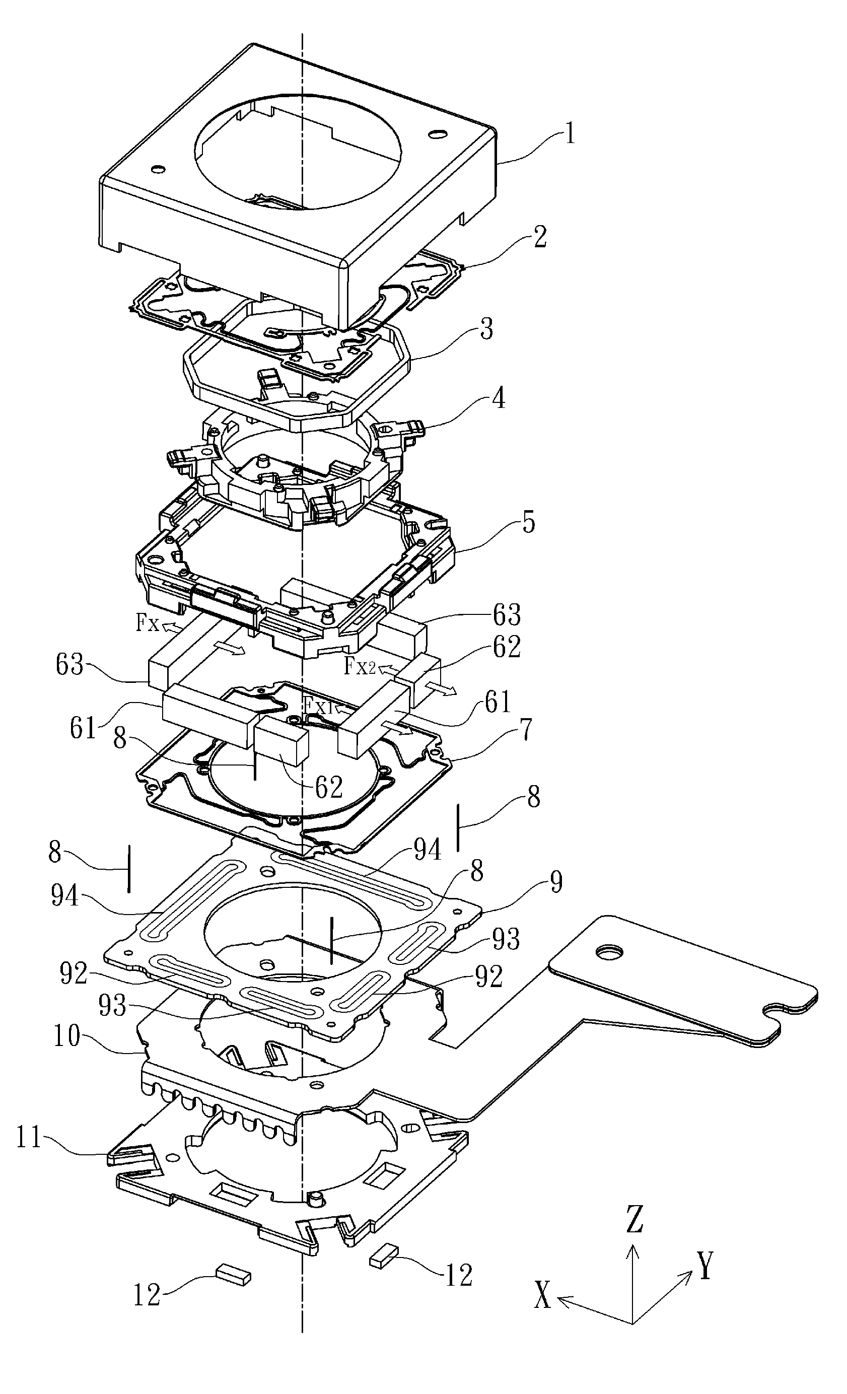
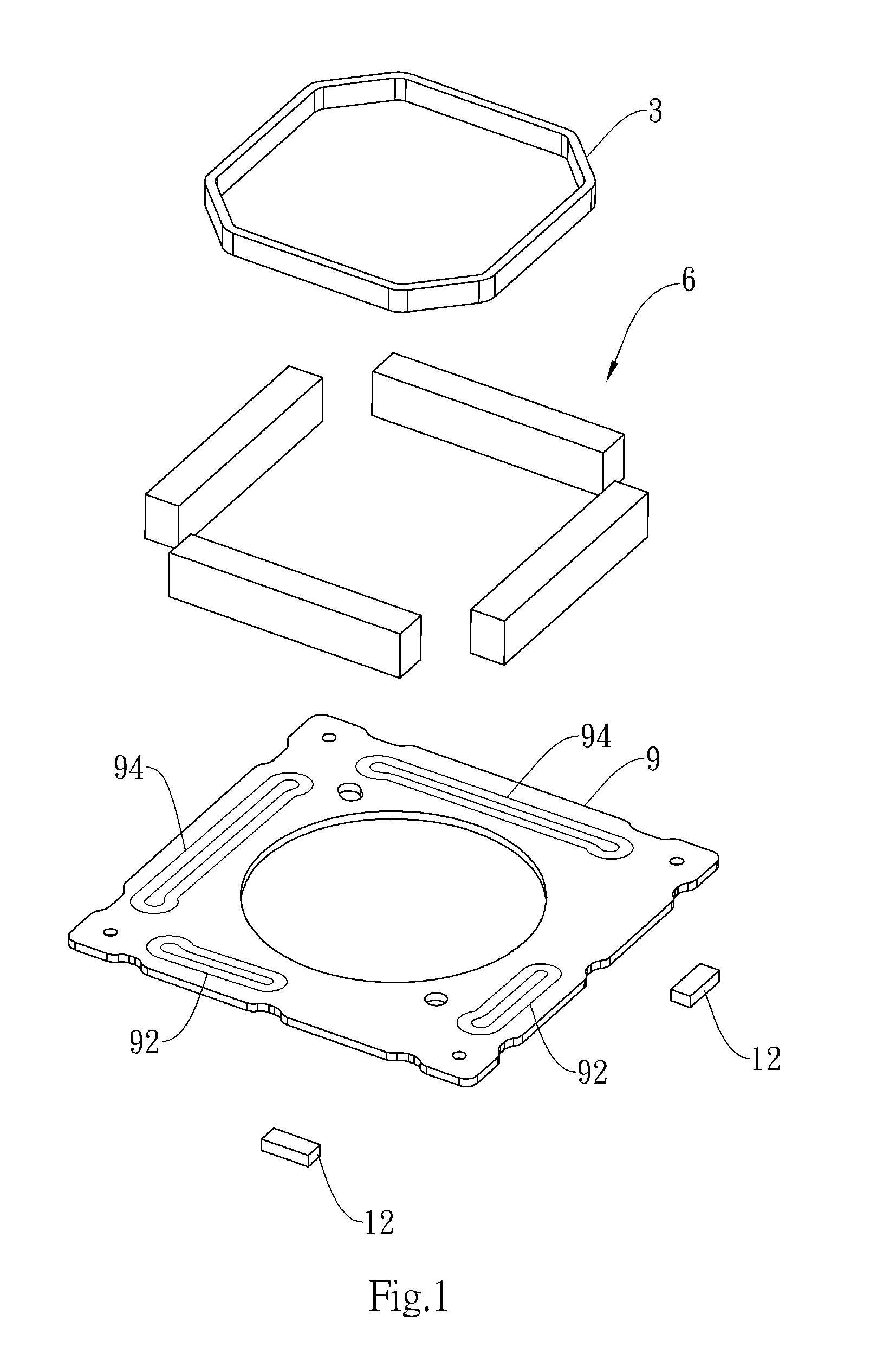
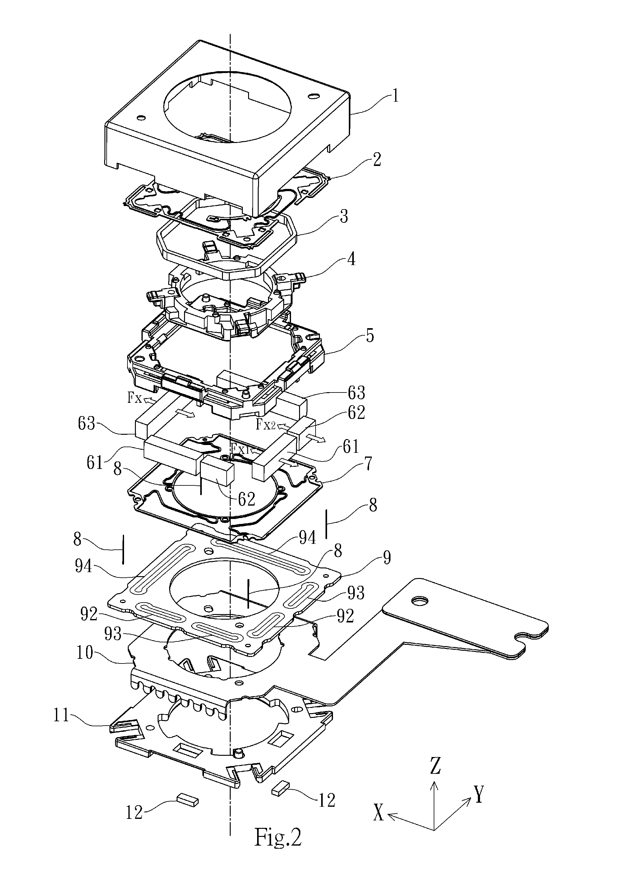
[0024]FIG. 2 is an exploded view showing the structure of an embodiment of the present invention, and the components illustrated therein are to be viewed by reference to the axes X, Y and Z. In this embodiment of the present invention, there is provided a lens driving device comprising, from top to bottom: an outer cover 1; an upper plate spring 2; a focusing coil 3; a lens holder 4; a frame 5; a plurality of magnets disposed at a periphery of the lens holder 4; a lower plate spring 7; a suspension ring wire 8; a coil plate 9 provided with a vibration correction coil set on one flat surface thereof; a flexible circuit board 10; a lower cover 11; and at least one Hall element 12; wherein the vibration correction coil set comprises a first vibration correction coil 92, a second vibration correc...


PUM

PropertyMeasurementUnit
Thicknessaaaaaaaaaa
Heightaaaaaaaaaa

Abstract

The present invention discloses a lens driving device and a method of manufacturing the same. In the present invention, there is provided a lens driving device comprising: a lens having an optical axis; a focusing coil disposed at a periphery of the lens with respect to the optical axis; a vibration correction coil set comprising a plurality of coils and disposed on a flat surface perpendicular to the optical axis; and a plurality of magnets disposed at the periphery of the lens with respect to the optical axis, each of which having a first surface facing the focusing coil and a second surface facing a corresponding one of respective coils of the vibration correction coil set; wherein the focusing coil acts on the first surface of each of the plurality of magnets to cause an assembly including the lens and the focusing coil to move in the optical axis direction with respect to the plurality of magnets; and wherein a direction in which one coil of the vibration correction coil set acts on the second surface of one of the plurality of magnets is the same as directions in which another two coils of the vibration correction coil set act respectively on the second surfaces of another two magnets of the plurality of magnets respectively so as to cause an assembly including the lens, the focusing coil and the plurality of magnets to move in a direction perpendicular to the optical axis with respect to the vibration correction coil set.

Description

BACKGROUND OF THE INVENTION[0001]1. Field of the Invention[0002]The present invention relates to a lens driving device, and more particularly, to a lens driving device capable of stabilizing and improving resonances and a method of manufacturing the same.[0003]2. Description of the Prior Art[0004]Those skilled in the art have endeavored to reduce or eliminate the negative impact on photos caused due to the shaking of the camera by the camera operator (the so-called hand shaking) during the photo taking session.[0005]It is commonly agreed that the fast developing optical anti-vibration technique will become the mainstream anti-vibration technique in the future because this technique can prevent drawbacks such as poor image quality as a result of the correction made with software and longer latency of software processing.[0006]In the field of optical anti-vibration, the significant “lens displacement based” optical anti-vibration method has advanced and developed rapidly in recent yea...

Claims


Application Information

Patent Timeline
IPC IPC(8): G02B7/04
CPCG02B7/04G02B7/08G02B27/646Y10T29/49009
Inventor HU, CHAO-CHANGCHEN, YI-HO
Owner TDK TAIWAN
Why Eureka
Try Eureka