A milling blank and a method for fabricating dental bridgework using milling blank

a technology of milling blanks and dental bridges, applied in the field of medical systems and methods, can solve the problems of high degree of skill and long time, inconvenient milling units for working on hard materials, and laborious labor for custom prostheses

Inactive Publication Date: 2015-01-22
EFTEKHAR ASHTIANI REZA +1
View PDF6 Cites 13 Cited by
  • Summary
  • Abstract
  • Description
  • Claims
  • Application Information

AI Technical Summary

Benefits of technology

[0022]The various embodiments herein provide a dental mill blank for fabrication of dental appliance and restorations. The mill blank comprises a hard inner core and wherein the hard inner core provides resistance against a normal occlusal force, a soft outer cover surrounding the inner core, a channel passing through the inner core and the outer cover, a metallic abutment provided at one end of the channel and a handle stud for holding the mill blank onto a milling machine. The channel is designed to make a screw type bridgework for supporting a plurality of neighboring implants.

Problems solved by technology

Thus, the fabrication of custom prosthesis involves intensive labor, high degree of skills and longer time periods.
The chair side systems have the benefit of same day delivery but the milling unit is not suitable to works on very hard materials.
So the usage of chair side machine is limited mostly to the single unit or intra-coronal restoration.
The physical properties, such as hardness and brittleness, of the currently used dental porcelain materials limit the usefulness of this material without a substructure for crown and bridge.
Chair side CAD / CAM is unable to shape very hard material easily.
So the use of this device is limited to softer or presenter ceramic and porcelain which could not be in high pressure situation such as long span bridge in anterior or posterior of the mouth, short span bridge in posterior area, short teeth or even anterior bridge.
Therefore the use of the device is only limited to inlay, onlay, single crown and short span bridge of anterior teeth, if only the tooth crown is long enough to let a bridge work have a joint diameter of 16 mm2.

Method used


Image

  • A milling blank and a method for fabricating dental bridgework using milling blank
  • A milling blank and a method for fabricating dental bridgework using milling blank
  • A milling blank and a method for fabricating dental bridgework using milling blank

Examples


Embodiment Construction

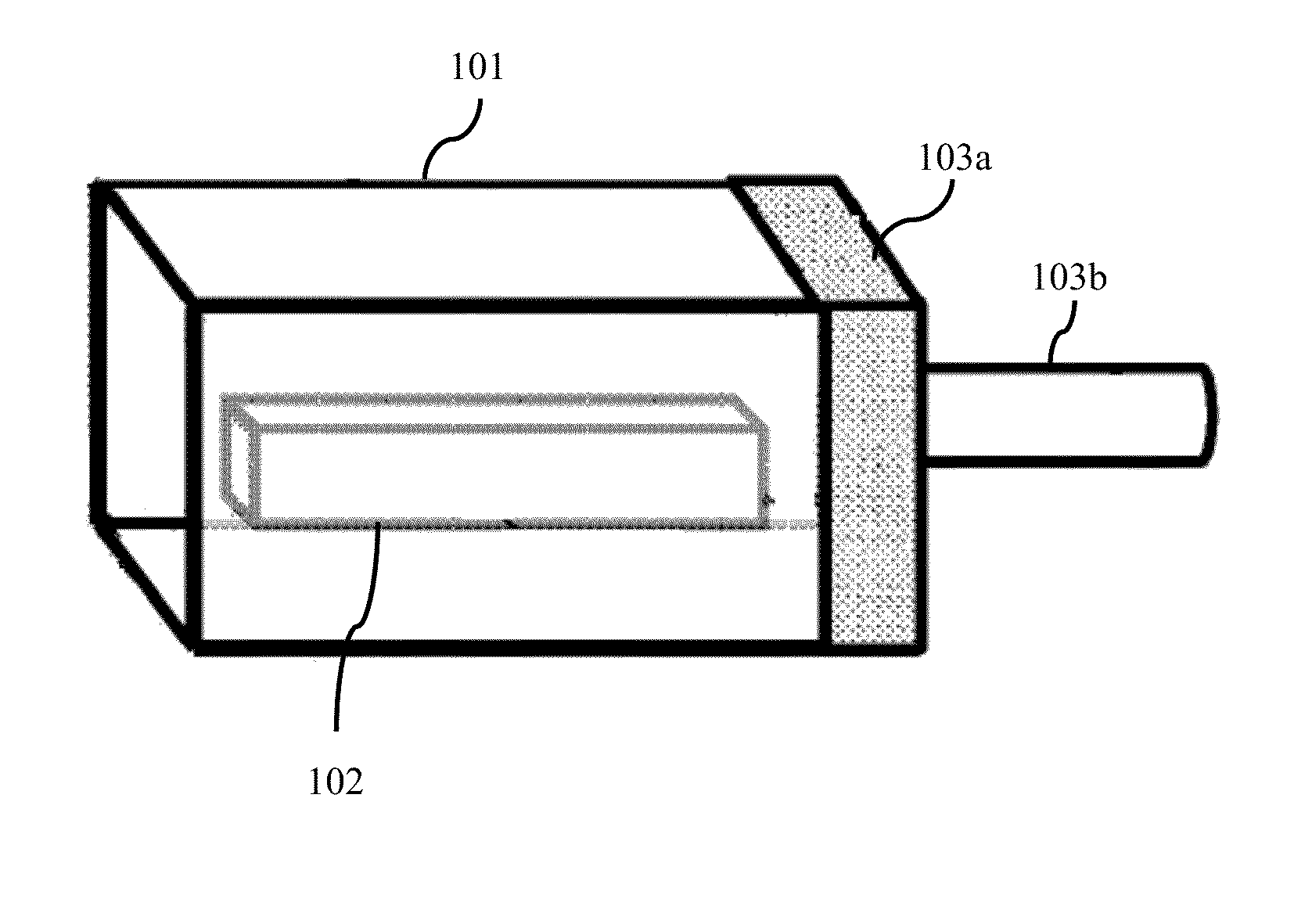
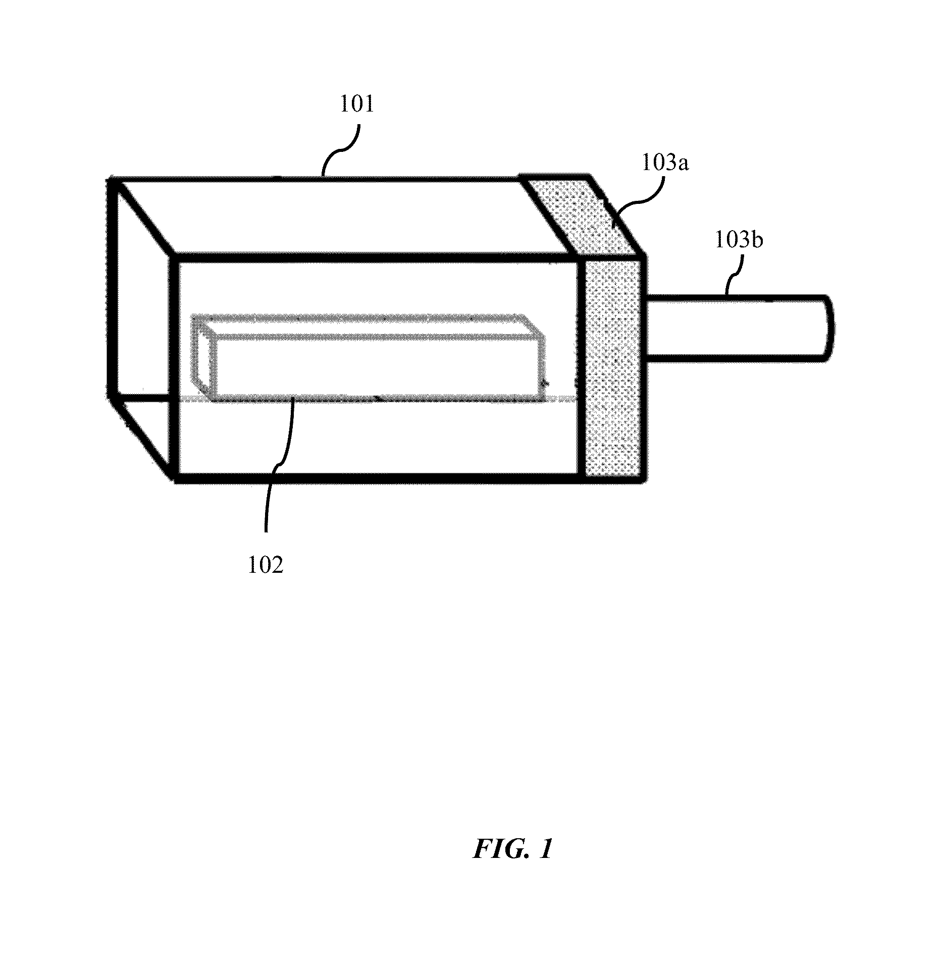
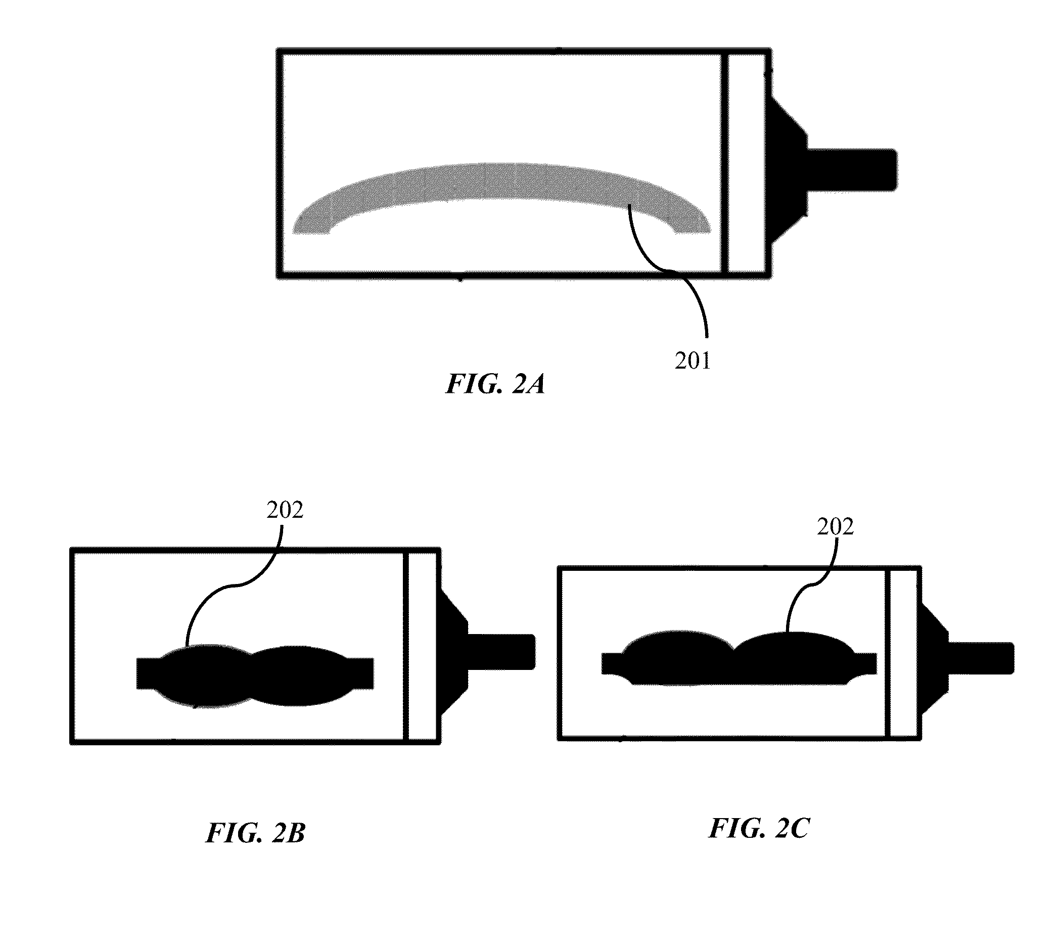
[0013]The primary object of the embodiments herein is to provide a mill blank for dental applications a method for fabricating dental bridgework using the mill blank.

[0014]Another object of the embodiments herein is to provide a dental restoration in digital format.

[0015]Yet another object of the embodiments herein is to provide a mill blank with dental bridgework having enough resistance for normal oral pressure or occlusal force.

[0016]Yet another object of the embodiments herein is to provide a mill blank with dental bridgework with a surface area of joint less than 16 mm2.

[0017]Yet another object of the embodiments herein is to provide a mill blank with outer cover made up of sintered or pre-sintered ceramics, composite or acrylic materials.

[0018]Yet another object of the embodiments herein is to provide a mill blank with a screw type bridge work for multiple neighboring implants.

[0019]Yet another embodiment of the present invention is to provide a method of fabricating a dental ...


PUM

PropertyMeasurementUnit
surface areaaaaaaaaaaa
fracture strengthaaaaaaaaaa
resistanceaaaaaaaaaa

Abstract

The various embodiments herein provide a dental mill blank for fabrication of dental appliance and restorations. A method for fabricating dental bridgework from the mill blank is also provided. The mill blank comprises a hard inner core and wherein the hard inner core provides resistance against a normal occlusal force, a soft outer cover surrounding the inner core, a channel passing through the inner core and the outer cover, a metallic abutment provided at one end of the channel and a handle stud for holding the mill blank onto a milling machine. The channel is designed to make a screw type bridgework for supporting a plurality of neighbouring implants.

Description

CROSS-REFERENCE TO RELATED APPLICATIONS[0001]The present application claims the benefit and the priority of the U.S. Provisional Patent Application with Ser. No. 61 / 928,885 and entitled, “MILLING BLANK WITH CENTRAL HARD CORE FOR BRIDGEWORK DESIGN AND METHODS”, filed on Jan. 17, 2014, the content of which is incorporated in entirety by reference herein.BACKGROUND[0002]1. Technical Field[0003]The embodiments herein generally relates to medical systems and methods. The embodiments herein particularly relates to a dental restoration systems and methods. The embodiments herein more particularly relates to a milling blank for dental applications and a method for fabricating a dental bridgework using the milling blank.[0004]2. Description of the Related Art[0005]The art of fabricating custom fit bridgework or fixed partial denture in the dental field is well known. This prosthesis is a replacement of the lost teeth with a help of an adjoining teeth. For the fabrication of this restoration,...

Claims


Application Information

Patent Timeline
Patent Type & Authority Applications(United States)
IPC IPC(8): A61C13/00A61C9/00A61C5/10A61C5/77
CPCA61C13/0022A61C5/10A61C9/004A61C13/0004A61C13/09G16H20/40
Inventor EFTEKHAR ASHTIANI, REZAEFTEKHAR ASHTIANI, ARYA
Owner EFTEKHAR ASHTIANI REZA
Why Eureka
Try Eureka