Surface stationary array coil structure for multi-modality imaging

a stationary array and imaging technology, applied in the field of medical imaging, can solve the problems of reducing the pet signal to the detector, degrading the image quality, and mutual annihilation, and achieve the effect of reducing image degradation and improving mr image quality

Active Publication Date: 2015-01-22
GENERAL ELECTRIC CO
View PDF1 Cites 14 Cited by
  • Summary
  • Abstract
  • Description
  • Claims
  • Application Information

AI Technical Summary

Benefits of technology

[0011]Embodiments of the invention provide a stand-alone MR system or combined PET-MR system incorporating a stationary posterior RF coil structure that provides patient support for moving over the PET region while reducing image degradation and improving MR image quality on the sides of the patient with wing-like structures with RF elements that follow the cradle contour.

Problems solved by technology

As these positrons travel through the tissues of the subject, they lose kinetic energy and ultimately collide with an electron, resulting in mutual annihilation.
That is, while in a standalone MR system the structure and mass of components within the bore has no effect on image acquisition and image quality, such is not the case in a PET-MR system—as the mass in the PET detector region attenuates gamma rays, which reduces PET signal to the detectors and degrades image quality (IQ).
Typically, any electronics associated with the stationary posterior RF coil structure, such as decoupling boards, feedboards, mux boards, and baluns for example, are positioned immediately adjacent the RF coil elements, and are thus also positioned at the center of the MR and PET FOV, thereby adding mass and additional components in the region of the PET detector and potentially reducing image quality.
Existing designs of the stationary posterior RF coil structure provide a flat configuration or construction that lacks the curvature that is normally found on the patient cradle, such that existing posterior coil structure designs fail to position the RF coil elements in close proximity to the patient anatomy or provide such a uniform gap between the coil elements and the patient surface on the cradle.

Method used


Image

  • Surface stationary array coil structure for multi-modality imaging
  • Surface stationary array coil structure for multi-modality imaging
  • Surface stationary array coil structure for multi-modality imaging

Examples


Embodiment Construction

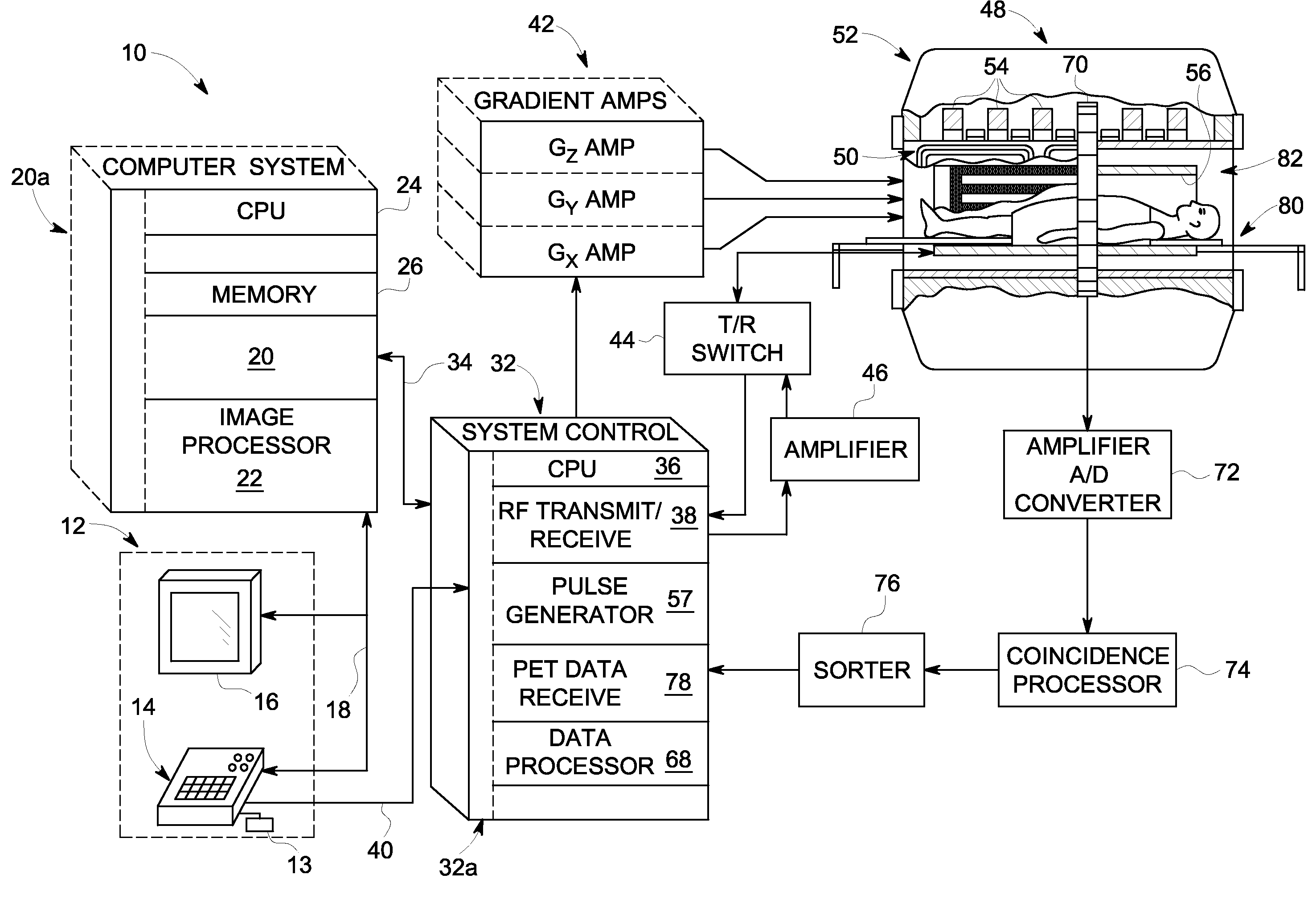
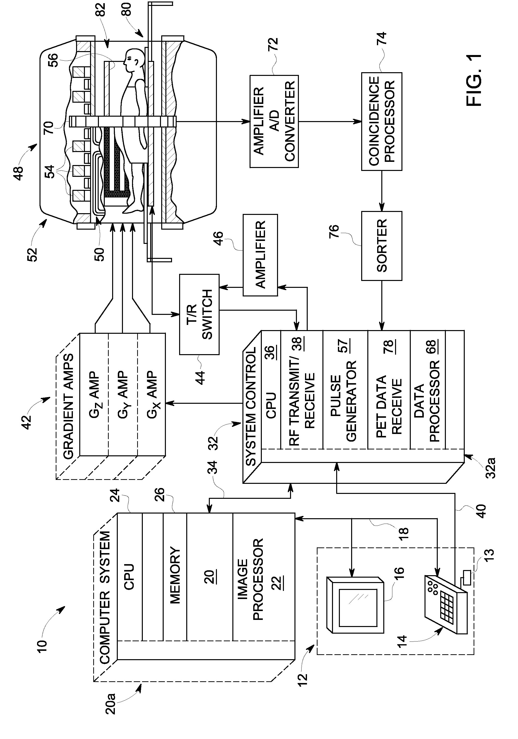
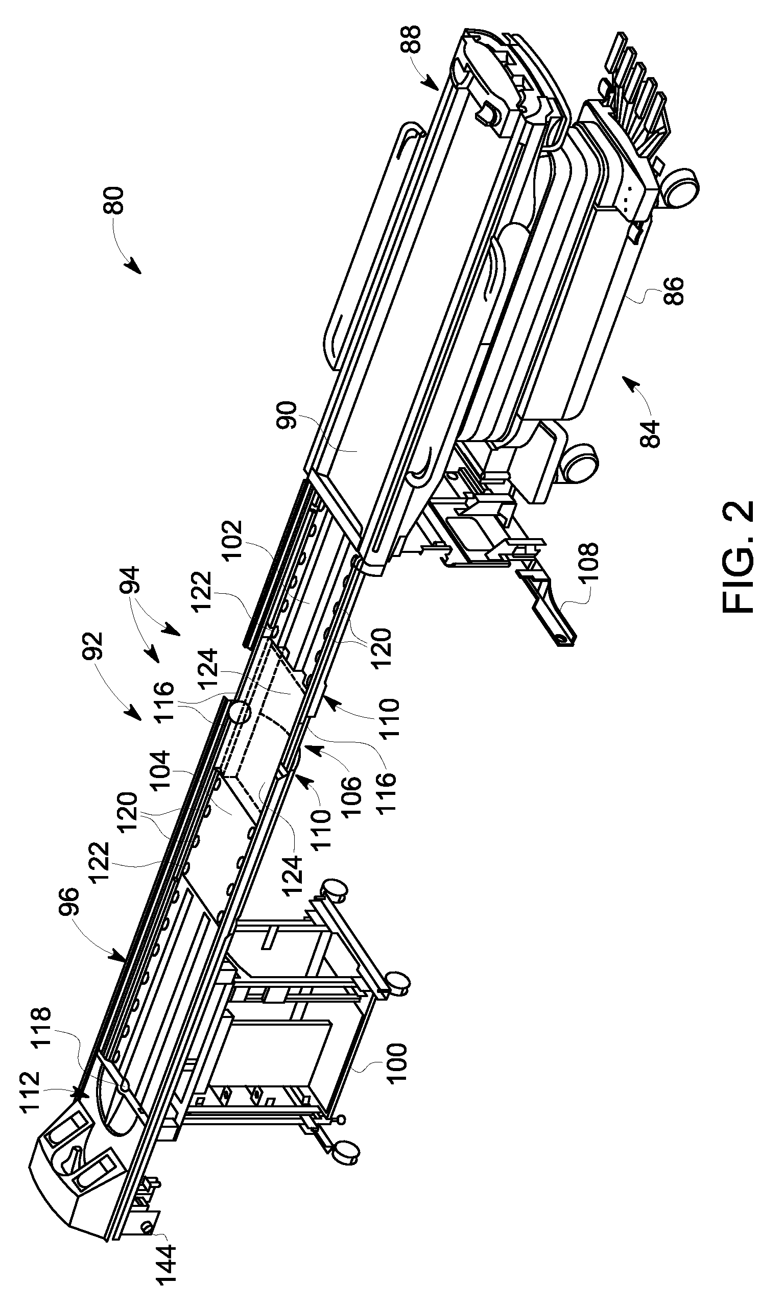
[0024]A stationary posterior RF coil structure for use in a stand-alone MR imaging system or hybrid PET-MR system is provided. The RF coil structure is constructed so as to arrange RF coil elements thereon so as to provide a constant and uniform gap between the entire set of RF elements and a patient cradle surface so as to enable good MR image quality. The RF coil structure is further constructed to include structural elements that enable the cradle to roll over the posterior stationary RF coil, as the cradle moves thru the magnet bore, without deforming the RF coil elements—so as to enable stable image quality with any patient mass. The stationary posterior RF coil structure is still further constructed to have a minimal mass in the PET detector region (i.e., PET gap) by providing minimal electrical and mechanical components in the PET gap and moving all large mass components away from the PET gap, so as to enable good PET image quality.

[0025]According to embodiments of the invent...


PUM


Abstract

A stand-alone MR or hybrid PET-MR imaging system incorporating a surface stationary RF coil structure is disclosed. The imaging system includes a support assembly comprising a cradle to accommodate a subject and a bridge to receive the cradle and provide for translation therealong to enable an acquisition of imaging data. An RF coil structure is positioned between the bridge and the cradle, and includes a base portion, a cover portion, and an array of RF coil elements positioned on the cover portion. The cover portion includes contoured features that enable placement of RF coil elements in proximity to a subject and to provide a constant and uniform gap between the RF elements and the cradle. The RF coil structure also includes structural elements that support the cradle when rolling over the array of RF coil elements without deforming the RF coil elements.

Description

BACKGROUND OF THE INVENTION[0001]Embodiments of the invention relate generally to medical imaging, and more specifically, to a stand-alone magnetic resonance (MR) imaging system or hybrid MR and positron emission tomography (PET) system incorporating a surface stationary RF coil structure that provides patient support while reducing image degradation.[0002]MR imaging involves the use of magnetic fields and excitation pulses to detect the free induction decay of nuclei having net spins. When a substance such as human tissue is subjected to a uniform magnetic field (polarizing field Bo), the individual magnetic moments of the spins in the tissue attempt to align with this polarizing field, but process about it in random order at their characteristic Larmor frequency. If the substance, or tissue, is subjected to a magnetic field (excitation field B1) which is in the x-y plane and which is near the Larmor frequency, the net aligned moment, or “longitudinal magnetization”, MZ, may be rot...

Claims


Application Information

Patent Timeline
Patent Type & Authority Applications(United States)
IPC IPC(8): A61B5/00A61B5/055
CPCA61B5/0555A61B5/0035G01R33/481G01R33/3415G01R33/34007A61B5/055A61B5/704
Inventor EMACI, EDWARDCALLOWAY, MICHAEL JAMES
Owner GENERAL ELECTRIC CO
Why Eureka
Try Eureka