Bearing stand-off devices

a stand-off device and bearing technology, applied in the direction of bearing unit rigid support, washing machine, manufacturing tools, etc., can solve the problems of reduced bearing life, unsanitary conditions, limited cleaning fluid potential, etc., to facilitate fluid exit, facilitate fluid access, and facilitate inspection

Inactive Publication Date: 2015-01-29
SOLUS INDAL INNOVATIONS
View PDF11 Cites 7 Cited by
  • Summary
  • Abstract
  • Description
  • Claims
  • Application Information

AI Technical Summary

Benefits of technology

[0009]Another way to space the bearing assembly from the frame is to use a bearing assembly that includes a housing with integral legs. When such a housing is secured with the frame, the legs space the remainder of the bearing assembly from the frame. However, this requires a specialized design for the housing of the bearing assembly. Moreover, to retrofit a conveyor system with bearing assemblies that are mated flush with the frame with bearing assemblies having legs would require replacing the original bearing assemblies, regardless of whether those assemblies are still operational. This can be inefficient and can incur cost, both in terms of money (e.g., to obtain the bearing assemblies with legs) and time (e.g., to remove each of the old bearing assemblies from the frame and the shafts and replace each with a bearing assembly with legs).
[0015]Certain embodiments of the stand-off device increase the amount of surface area accessible by cleaning fluid compared to some bearing housings with legs. Some leg bearing housings have a relatively large surface area that contacts the conveyor side frame, thereby leaving more area generally inaccessible by cleaning fluid. In contrast, the size of the portion of the stand-off device that contacts the frame can be reduced, thereby allowing more exposure of the conveyor side frame to the cleaning fluid.

Problems solved by technology

This can be problematic because pathogens (e.g., bacteria and viruses) and small contaminants (e.g., dust, dirt, portions of conveyed product, etc.) can penetrate between the frame and the bearing assembly.
This can lead to unsanitary conditions.
Moreover, even if the conveyor system is washed with cleaning fluid, because the back face of the bearing assembly is flush against the frame, there is limited potential for the cleaning fluid to access the area between the bearing assembly and the frame.
Thus, the bacterial growth and contaminant accumulation can continue, which can lead to a reduction in bearing life, failures of cleanliness inspection, health code violations, or other issues.
Furthermore, mounting the bearing assembly directly to the frame can result in fluid (e.g., cleaning liquid) that penetrates between the bearing assembly and the frame being held there, such as by weeping or capillary action.
This can lead to corrosion of the bearing assembly and / or frame, growth of mold or other organisms, or other issues.
As the bolt and nut are secured, the washer provides a physical interference that stops the bearing assembly from being mated flush against the frame.
However, use of such a washer can be clumsy and is inconvenient.
For example, use of the washer requires the installer to manage and manipulate (e.g., align the holes of) the bearing assembly, washer, frame, and nut, which can be difficult.
The difficulty can be exacerbated in the not uncommon situation in which the bearing assembly is positioned in a location with tight spacial constraints and / or limited visibility.
Thus, aligning the washer with all of the other components can be difficult and / or impractical.
However, this requires a specialized design for the housing of the bearing assembly.
This can be inefficient and can incur cost, both in terms of money (e.g., to obtain the bearing assemblies with legs) and time (e.g., to remove each of the old bearing assemblies from the frame and the shafts and replace each with a bearing assembly with legs).
When the bearing housing is mated with a frame, such as the frame of a conveyor system, the spacing portion can provide a physical interference that limits how closely the bearing housing can be mated with the frame, thereby providing space between the bearing housing and the frame.
As noted above, one approach is to use thick washers, which can be clumsy and can increase the difficulty of installing the bearing assembly.
This can be difficult and time-consuming, especially in installing bearing assemblies in hard-to-reach places, places with little space for movement, limited visibility, or other factors that make the installation more difficult and / or complex.
Some leg bearing housings have a relatively large surface area that contacts the conveyor side frame, thereby leaving more area generally inaccessible by cleaning fluid.
However, not all embodiments include or achieve any or all of those aspects, advantages, and features.

Method used


Image

  • Bearing stand-off devices
  • Bearing stand-off devices
  • Bearing stand-off devices

Examples


Embodiment Construction

[0031]Various embodiments of stand-off devices are described herein. Certain embodiments are discussed in the context of mating bearing assemblies with conveyor frames, due to particular utility in that context. However, the inventions disclosed herein can be used in other contexts as well, such as to mate bearing assemblies—or other types of assemblies—with other types of structures, such as frames or housings of non-conveyor systems. Further, although the inventions are described herein in reference to various embodiments and drawings, such embodiments and drawings are not intended to be limiting. On the contrary, variations and improvements may be accomplished in view of these teachings without deviating from the scope and spirit of the invention and are within the scope of this disclosure.

Overview

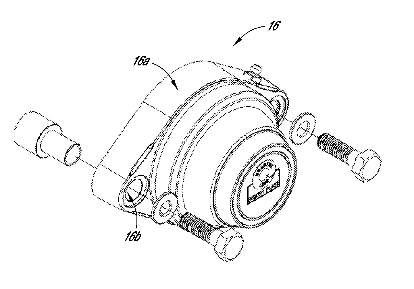
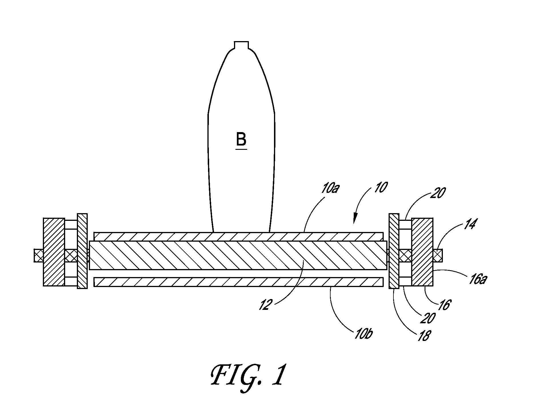
[0032]FIG. 1 shows an illustrative conveyor system including a stand-off device 20, with the view being generally parallel to the direction of belt travel. As shown, the system includes...


PUM

PropertyMeasurementUnit
length L2aaaaaaaaaa
length L2aaaaaaaaaa
length L2aaaaaaaaaa

Abstract

Various embodiments of stand-off devices and methods are disclosed. The stand-off device can space a bearing assembly apart from a support, such as a frame of a conveyor belt, thereby providing access between the bearing assembly and the frame, such as for cleaning fluid. Certain embodiments of the stand-off device include a first end and a second end, with the first end being receivable in a securing hole of the bearing assembly and the second end configured to protrude from the bearing assembly.

Description

CROSS REFERENCE TO RELATED APPLICATION[0001]The present application claims the priority benefit under at least 35 U.S.C. §119 of U.S. Patent Application No. 61 / 858,993, filed Jul. 26, 2013, the entirety of which is incorporated by reference herein.BACKGROUND[0002]1. Field[0003]The present disclosure relates to facilitating access to portions of processing equipment, such as access for cleaning fluid between a bearing assembly and a frame.[0004]2. Description of the Related Art[0005]Processing equipment, such as conveyor systems, is used for a variety of purposes. For example, conveyor systems are used to transport articles from a first location to a second location. These systems can include a conveyor belt (or chain) that is arranged in an endless loop and driven to convey the objects on the belt surface. The belt can be supported by rotatable elements, such as rollers, at certain locations along the length of the belt. Portions of the rollers can be journaled (e.g., installed) in ...

Claims


Application Information

Patent Timeline
Patent Type & Authority Applications(United States)
IPC IPC(8): B23P15/00
CPCB23P15/003F16C35/02F16C35/045F16B43/00F16C13/02F16B19/02B08B13/00Y10T29/49679Y10T29/53104B65G39/09F16C2235/00F16C35/00F16C43/00
Inventor EURE, TOMPHILLIPS, SCOTT
Owner SOLUS INDAL INNOVATIONS
Why Eureka
Try Eureka