Water-cooled dosing module

a technology of water-cooled dosing module and dosing valve, which is applied in the direction of engines, mechanical equipment, machines/engines, etc., can solve the problems of inability to achieve cooling effect in the top region, possible outage of valve and/or electrical contact means of dosing valve, etc., and achieve high variability, high variance, and high variability

Active Publication Date: 2015-01-29
ROBERT BOSCH GMBH
View PDF7 Cites 13 Cited by
  • Summary
  • Abstract
  • Description
  • Claims
  • Application Information

AI Technical Summary

Benefits of technology

[0009]In the case of the solution proposed according to the invention, in which the valve is encased by a full enclosure, coolant coming from the vehicle is introduced first of all into the lower cooling member, ensuring that the maximum cooling capacity is available at the hottest point, i.e. at the valve tip of the valve. As a result, optimum cooling of the valve tip region of the dosing module proposed according to the invention is achieved. From the lower cooling member, the cooling fluid, which has now been heated through heat absorption owing to the cooling of the valve tip, crosses into the upper, additional cooling member on the inside in the region of the laser weld. Thus the upper region of the dosing module, in which the electrical connection and the magnet coil are located, can also be cooled. In a manner that is advantageous in terms of production, the full enclosure according to the solution proposed according to the invention can be produced entirely by means of deep-drawn and bent parts, allowing low-cost production of the full enclosure proposed according to the invention surrounding the dosing module.
[0012]Owing to this variability in the position of the cooling water inlet, of the cooling water outlet and of the reducing agent feed, it is possible to allow for the restricted installation space conditions in the engine compartment of vehicles. Through the high variability in the cooling water feeds and cooling water outlets, it is furthermore possible to ensure high variance, i.e. high variability in respect of different customer requirements, depending on the available installation space. Moreover, it is advantageously possible by means of the solution proposed according to the invention to achieve a situation where, by virtue of the full enclosure, cooling of the dosing module is also ensured in the region of the electrical contact means thereof.
[0013]As already explained above, the advantages of the solution proposed according to the invention consist in an increased temperature stability of the dosing module proposed according to the invention, allowing it to be installed even in the engine compartment of a vehicle. Moreover, the high variance in the location of the cooling water feeds or of the reducing agent feed makes it possible to allow for different installation conditions in the engine compartment of vehicles.
[0014]As a further advantage of the solution proposed according to the invention, it should be mentioned that a smaller cross section of the cooling member can be achieved through radial mounting of the cooling water connections. This, in turn, leads to a smaller design for the sealing and / or fastening region. It is thereby possible, in turn, to use a smaller seal and a smaller clamp, this having a favorable effect on the installation space, thus enabling better account to be taken of customer installation space requirements.

Problems solved by technology

One disadvantage of this embodiment is the absence of a cooling effect in the top region, i.e. in the region of the electrical contact means of the dosing valve.
As a result, it is not possible to use this dosing module in ambient temperatures above 160° C. The electrical plug connection and the coil of the dosing valve are subject to damage at temperatures above 160° C., and therefore an outage of the valve and / or of the electrical contact means of the dosing valve may be expected.

Method used


Image

  • Water-cooled dosing module
  • Water-cooled dosing module
  • Water-cooled dosing module

Examples


Embodiment Construction

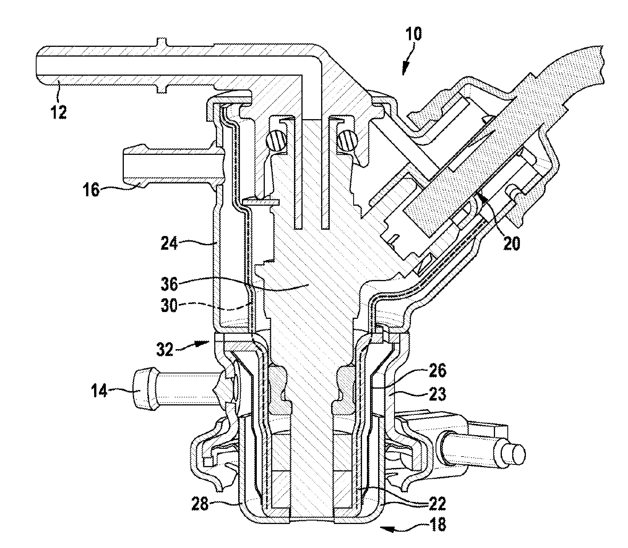
[0022]A dosing module 10 proposed according to the invention is used to meter a reducing agent into the exhaust system of an internal combustion engine. By means of the reducing agent, the NOx constituents contained in the exhaust gas from the internal combustion engines are reduced to H2O and N2. As a reducing agent, use is made primarily of aqueous urea solutions or other urea mixtures. One known reducing agent is known by the trade name AdBlue® and is used in dosing systems of this kind

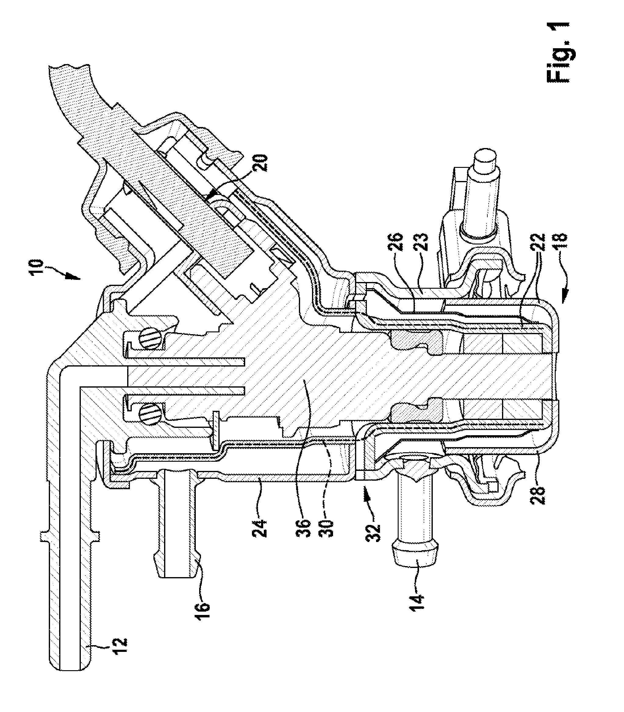
[0023]FIG. 1 shows a section through a dosing module 10, which is provided with a full enclosure and comprises a lower cooling member and an upper cooling member.

[0024]The section according to FIG. 1 shows a dosing module, in the upper region of which there extends a laterally projecting reducing agent feed. Via the reducing agent feed 12, the reducing agent flows to a dosing valve 36 of the dosing module 10. The dosing valve 36 of the dosing module 10 is contacted electrically via an electrical co...


PUM


Abstract

The invention relates to a dosing module (10) for metering a reducing agent into an exhaust system of an internal combustion engine. Said dosing module (10) comprises at least one cooling member (22, 24) through which a cooling fluid flows that is used to cool the internal combustion engine. An electric contact (20) is located in the top region of the dosing module (10). The dosing module (10) is enclosed in a full housing (38) that comprises an upper and a lower cooling member (22, 24,24) through which a directed cooling fluid stream (34) flows that runs from the valve tip region (18) in the direction of the electric contact (20).

Description

BACKGROUND OF THE INVENTION[0001]DE 44 36 397 A1 relates to a device for aftertreating exhaust gases. It discloses a device for aftertreating the exhaust gases from a self-ignition internal combustion engine, in which, to improve the operation of a catalyst with a reducing action, a reducing agent is added to the exhaust gas fed to the catalyst. Here, the reducing agent is added by means of an electrically controlled dosing valve, which is combined in a common housing with a control valve. This control valve is used for the controlled introduction of compressed air supplied, in which a quantity of reducing agent supplied via the dosing valve is prepared and added intermittently to the exhaust gas. This serves, in particular, to avoid urea deposits and adhesions on the dosing valve and the control valve as well as to ensure optimum preparation of the reducing agent introduced.[0002]DE 198 56 366 C1 relates to a device and to a method for aftertreating exhaust gases from an internal c...

Claims


Application Information

Patent Timeline
Patent Type & Authority Applications(United States)
IPC IPC(8): F01N3/20
CPCF01N3/208F01N3/2066F01N2260/024F01N2610/02F01N2610/11F01N2610/1453Y02T10/12
Inventor WINKLER, JOCHENKNITTEL, ACHIMPOHL, STEPHANKIONTKE, MARTIN
Owner ROBERT BOSCH GMBH
Why Eureka
Try Eureka