
Router Jig for Producing Tenons

a tenon and router technology, applied in the field of wood furniture creation, can solve the problems of time-consuming and labor-intensive cutting of tenons on logs with a larger diameter, limited range is especially problematic, and the use of hand saws can be stressful

Inactive Publication Date: 2015-01-29
SMITH LESLIE G
View PDF7 Cites 7 Cited by
  • Summary
  • Abstract
  • Description
  • Claims
  • Application Information

AI Technical Summary

Benefits of technology

The present invention is a device that can be used to cut tenons on logs with a straight line and different diameters. It eliminates the need for a vise or similar mechanical apparatus and allows users of different strengths to easily cut tenons. The device includes a motor and a threaded rod to create a secure and precise cut. It also allows for the simultaneous use of different router bits to create multiple cuts on a log. The invention is designed to improve efficiency and safety in the wood furniture industry.

Problems solved by technology

Since a vise can only expand in a limited range, only a limited number of logs can be mounted onto a vise.
The limited range is especially problematic when cutting tenons on a log with a larger diameter or a bent log.
However, using a hand saw can be stressful and is only possible for a limited number of logs.
For example, cutting a tenon on a log with a larger diameter may be time consuming due to its rigidness.
In almost all tenon cutting methods a well known issue is the inability to cut tenons of different diameters simultaneously.
Another issue that arises in tenon cutting is the strength of the user handling the log.
In particular, if the log has a significant weight, users of less strength will have difficulty in controlling the log while cutting a tenon or a shoulder on the log.
In unfortunate circumstances, the difficulty in handling can result in injuries to the user.
As a result, there is a high probability for the log to spin out of the vise, which can be risky to the user.

Method used


Image

  • Router Jig for Producing Tenons
  • Router Jig for Producing Tenons
  • Router Jig for Producing Tenons

Examples


Embodiment Construction

[0019]All illustrations of the drawings are for the purpose of describing selected versions of the present invention and are not intended to limit the scope of the present invention.

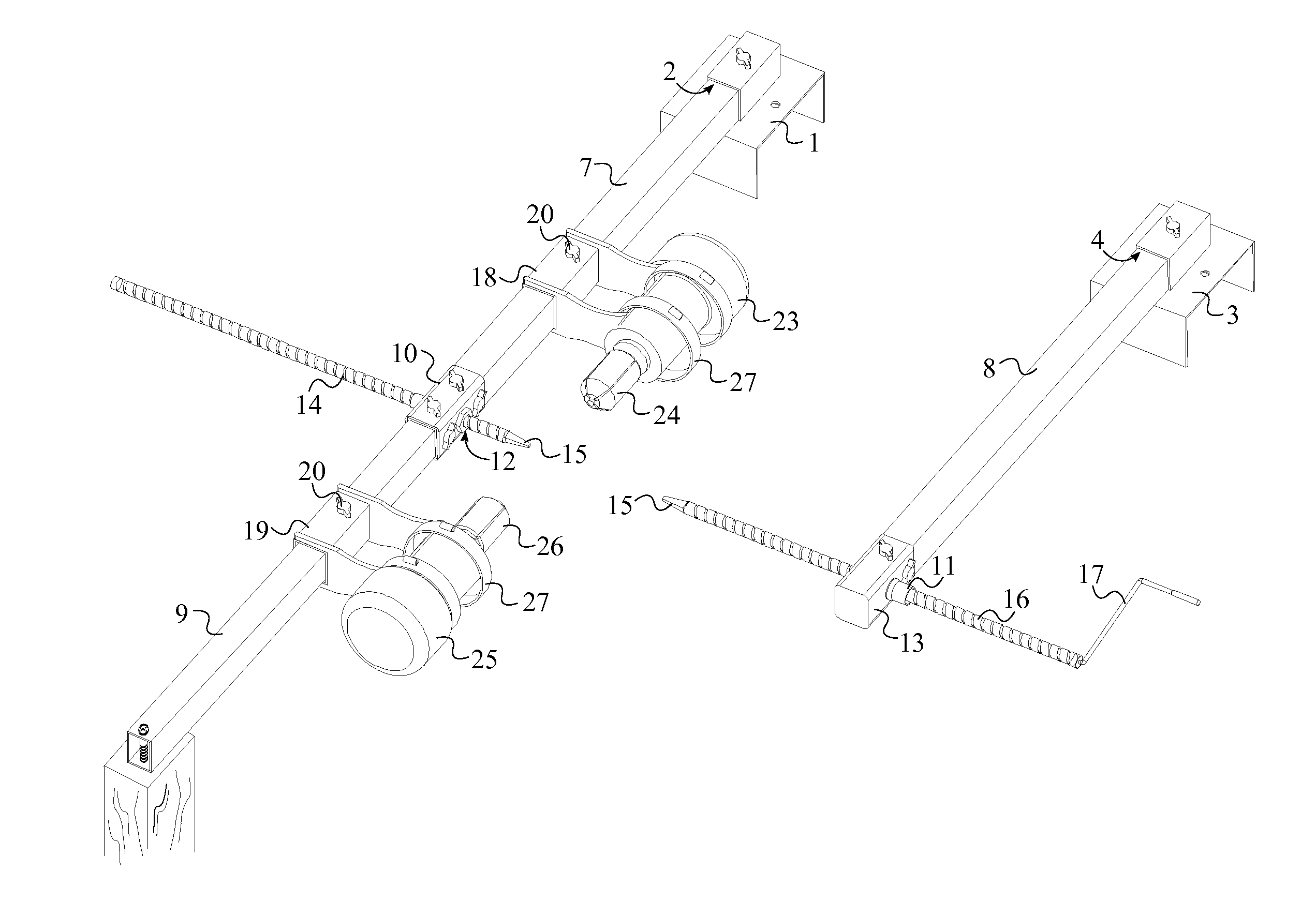
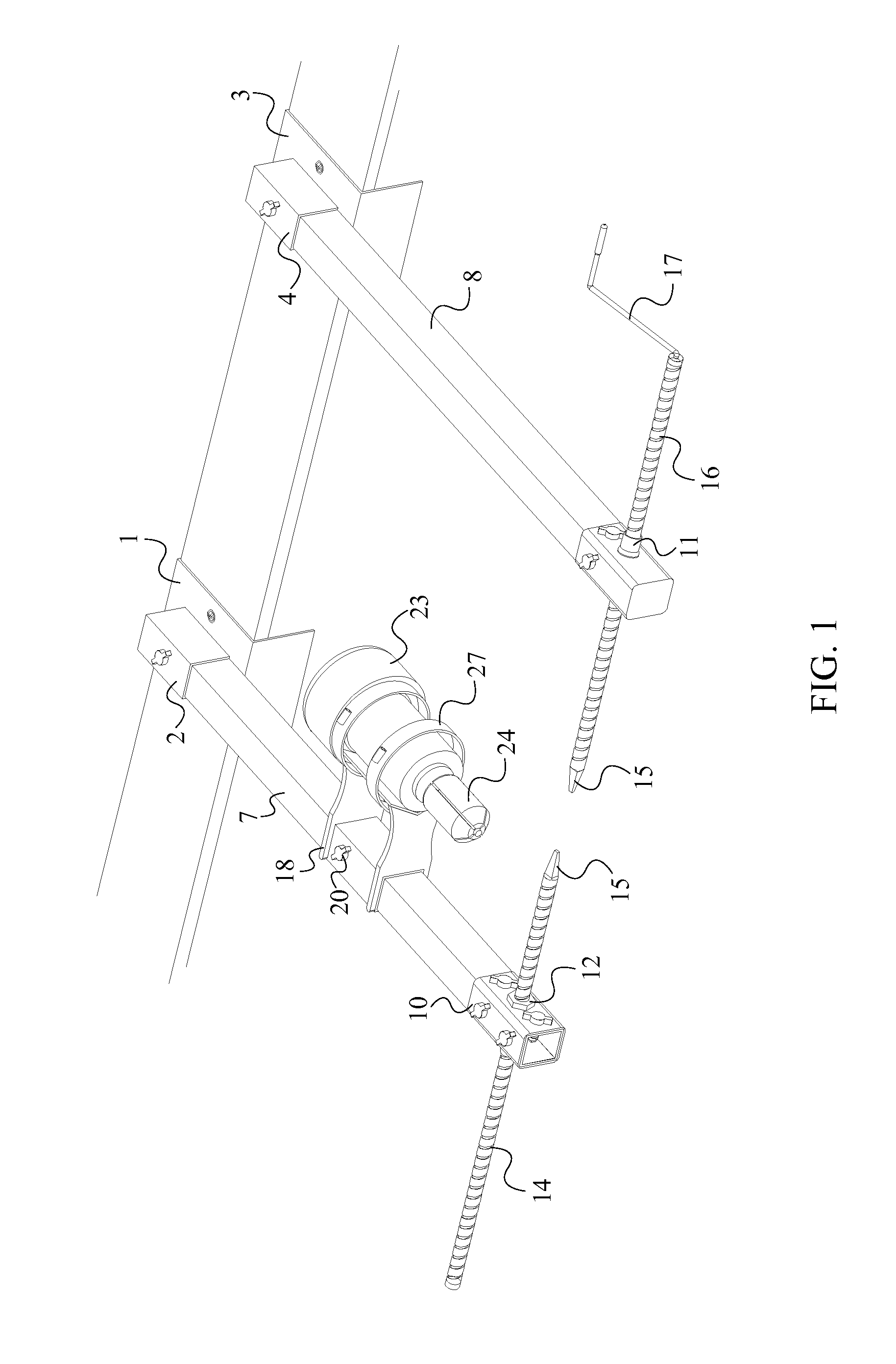
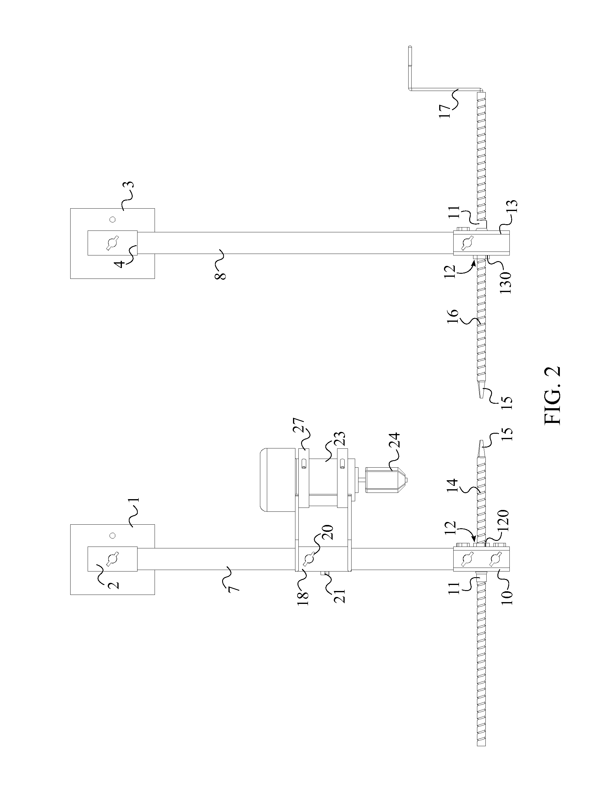
[0020]The present invention is an apparatus that can be used to cut straight tenons on logs that can vary in length, diameter, and shape. The present invention comprises a first bench mounting bracket 1, a first motor mounting bracket 18, a first motor 23, a first arm 7, a first threaded rod 14, a first rod holder 10, and a first router bit 24. As seen in FIG. 1, the first bench mounting bracket 1 is utilized to attach the present invention to an external platform such that the present invention remains steady during the tenon cutting process. The log in which a tenon is intended to be cut on, is placed adjacent to the first threaded rod 14 such that a tenon can be cut by utilizing the first router bit 24 connected to the first motor 23.

[0021]The present invention comprises a first configuration, a secon...


PUM


Abstract

An apparatus used for cutting tenons consists of a plurality of mounting brackets, a plurality of arms, a motor, and a pair of threaded rods. The plurality of mounting brackets attaches the apparatus to an external platform. The motor is mounted onto one of the plurality of arms allowing the motor to slide along the length of the arm. The log in which the tenon is to be cut is placed in between the pair of threaded rods. By rotating the log with the use of one of the threaded rods or with the use of a drill, the log makes contact with the motor. The rotating motion of both the log and also the motor, results in a tenon being cut on the log. Additionally, two motors can also be used in tenon cutting such that a tenon with different diameters can be cut simultaneously.

Description

[0001]The current application claims a priority to the U.S. Provisional Patent application Ser. No. 61 / 857,634 filed on Jul. 23, 2013.FIELD OF THE INVENTION[0002]The present invention relates generally to devices used in the field of creating wood furniture. More specifically, the present invention is a router jig that can be used to conveniently create tenons on logs.BACKGROUND OF THE INVENTION[0003]The mortise and tenon joint is a widely used method of joining two pieces of wood. This particular method has been a favorite among woodworkers mainly due to its simplicity and its effectiveness. The mortise and tenon joint mainly consists of a mortise hole and a tenon tongue. The tenon which is formed at the end of a log, usually referred as the rail, is inserted into a square or rectangular hole cut in the corresponding member. The tenon is formed to fit firmly within the corresponding mortise hole. Usually, the tenon has shoulders that lie flush against the surface area surrounding t...

Claims


Application Information

Patent Timeline
IPC IPC(8): B27F1/08
CPCB27F1/08B27C7/005B27F1/10B27L1/10
Inventor SMITH, LESLIE G.
Owner SMITH LESLIE G
Learn More