Casing and manufacturing method thereof

a manufacturing method and technology of a casing, applied in the direction of electric apparatus casings/cabinets/drawers, furniture parts, instruments, etc., can solve the problems of low yield, slow processing speed, and the inability to meet the requirements of mass production, and achieve the effect of simple manufacturing and good structural strength

Active Publication Date: 2015-01-29
WISTRON CORP
View PDF6 Cites 0 Cited by
  • Summary
  • Abstract
  • Description
  • Claims
  • Application Information

AI Technical Summary

Benefits of technology

[0007]The invention provides a casing and a manufacturing method thereof, which simplify the manufacture of the casing and endowing the casing with good structural strength.
[0022]Based on the above, the casing of the invention mainly consists of the plate, the frame and the main shell, wherein the adhering region of the plate is not overlapped with the frame, and the thermal fusion region of the plate is overlapped with the frame. Accordingly, the frame and the adhering region of the plate may be fixed to the main shell by adhesion. Furthermore, the thermal fusion region of the plate may be fixed to the frame by thermal fusion, thus providing the casing with good structural strength. As described above, the casing of the invention is manufactured by combining the plate, the frame with the main shell in a composite process (including adhesion and thermal fusion) instead of using a milling process that takes more time and effort. Therefore, the manufacturing of the casing is effectively improved in processing speed and yield, thereby reducing the manufacturing cost and facilitating mass production of the casing.

Problems solved by technology

However, in terms of the manufacture of the casings by means of milling, a huge number of processing machines are required, and moreover, problems such as slower processing speed, lower yield, and little feasibility of mass production may occur.

Method used


Image

  • Casing and manufacturing method thereof
  • Casing and manufacturing method thereof
  • Casing and manufacturing method thereof

Examples


Embodiment Construction

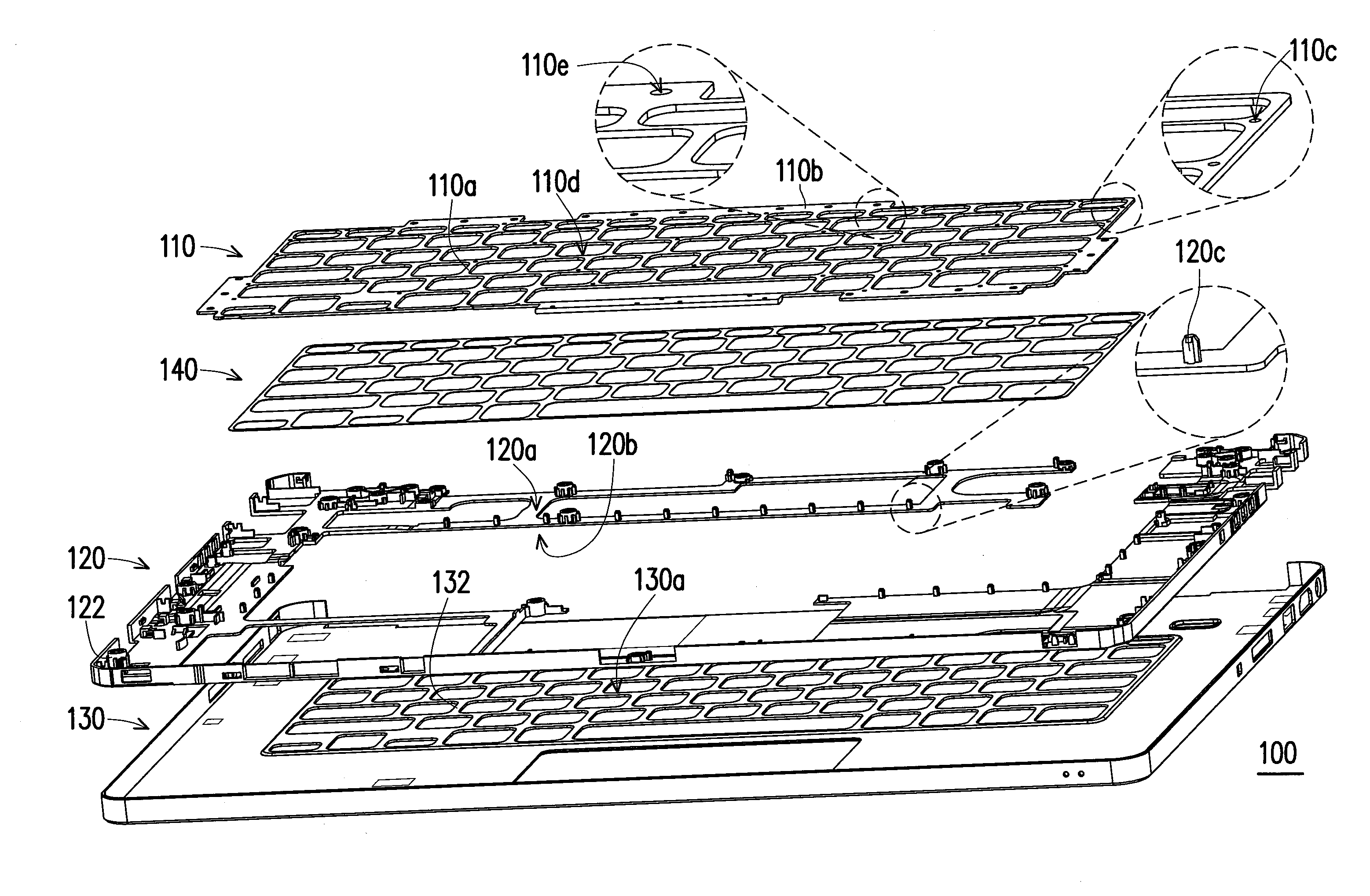
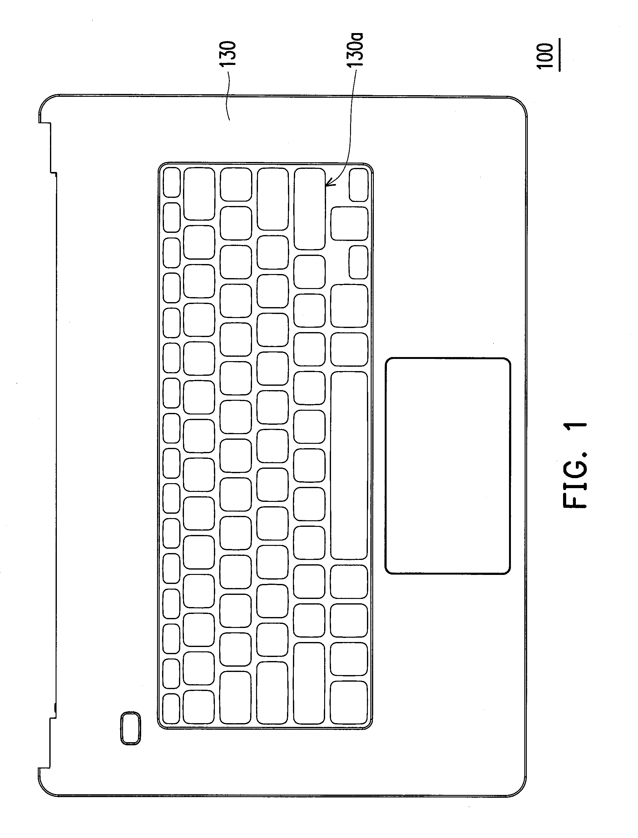
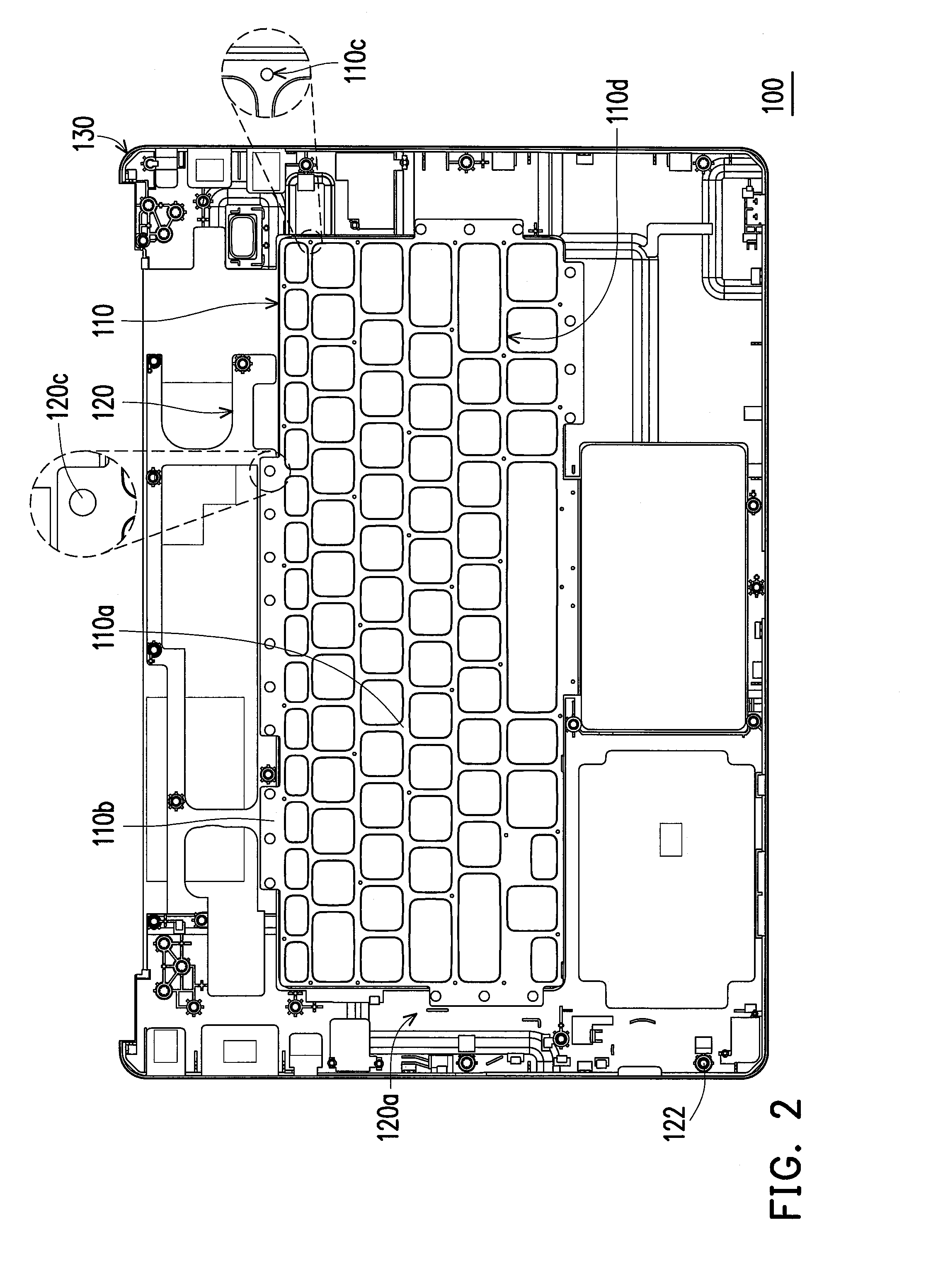
[0032]FIG. 1 is a top view of a casing according to an embodiment of the invention. FIG. 2 is a bottom view of the casing in FIG. 1. FIG. 3 is an exploded view of the casing in FIG. 1. Please refer to FIG. 1 to FIG. 3. In the present embodiment, a casing 100 is a casing of a main unit of a notebook computer, for example, and includes a plate 110, a frame 120 and a main shell 130. The plate 110 has an adhering region 110a and at least one thermal fusion region 110b (a plurality of thermal fusion regions 110b are illustrated in the drawings). The frame 120 has a first surface 120a and a second surface 120b opposite to each other. The plate 110 is stacked on the first surface 120a of the frame 120, wherein the thermal fusion region 110b of the plate 110 is connected to a periphery of the adhering region 110a and is fixed to the frame 120 by thermal fusion. The main shell 130 is adhered to the adhering region 110a of the plate 110 and the second surface 120b of the frame 120. The frame ...


PUM

PropertyMeasurementUnit
thicknessaaaaaaaaaa
adhesiveaaaaaaaaaa
thermalaaaaaaaaaa

Abstract

A manufacturing method of a casing is provided. First, a plate, a frame and a main shell are provided, wherein the plate has an adhering region and at least one thermal fusion region, and the frame has a first surface and a second surface opposite to each other. Then, the plate is stacked on the first surface of the frame, wherein the thermal fusion region is overlapped with the frame, and the adhering region is not overlapped with the frame. The main shell is adhered to the adhering region of the plate and the second surface of the frame. The thermal fusion region is fixed to the frame by thermal fusion. In addition, a casing manufactured through the above-mentioned method is also provided.

Description

CROSS-REFERENCE TO RELATED APPLICATION[0001]This application claims the priority benefit of Taiwan application serial no. 102126706, filed on Jul. 25, 2013. The entirety of the above-mentioned patent application is hereby incorporated by reference herein and made a part of this specification.BACKGROUND[0002]1. Field of the Invention[0003]The invention generally relates to a casing and a manufacturing method thereof, and more particularly to a casing of an electronic device and a manufacturing method thereof.[0004]2. Description of Related Art[0005]Thanks to advances in semiconductor devices and display technology, electronic devices have been continuously developed to be compact, capable of performing multiple functions, and easy to carry. Common portable electronic devices include tablet PCs, smart phones, notebook computers, and so forth. Notebook computers have the same functions as desktop computers, and are thus popular in the consumer market of electronic products.[0006]With a...

Claims


Application Information

Patent Timeline
Patent Type & Authority Applications(United States)
IPC IPC(8): G06F3/02H05K13/00
CPCH05K13/0023G06F3/0202G06F1/1658G06F1/1662G06F1/203Y10T29/49963Y10T29/49964Y10T29/49966H05K5/0247H05K13/00
Inventor LIU, LI-WEIYU, LIANG
Owner WISTRON CORP
Why Eureka
Try Eureka