Spherical Aberration Corrector, Method of Spherical Aberration Correction, and Charged Particle Beam Instrument

a technology of spherical aberration and corrector, which is applied in the direction of instruments, beam deviation/focusing by electric/magnetic means, optical elements, etc., can solve the problems of affecting the accuracy of the adjustment, the deviation of the circularity of the image or diffraction pattern, and the inability to adjust both the deviation of the circularity and the on-axis aberration, etc., to achieve good image and diffraction pattern less

Active Publication Date: 2015-01-29
JEOL LTD
View PDF12 Cites 6 Cited by
  • Summary
  • Abstract
  • Description
  • Claims
  • Application Information

AI Technical Summary

Benefits of technology

[0038]This charged particle beam instrument includes the spherical aberration corrector associated with the present invention and, therefore, it is possible to obtain good image and diffraction pattern less affected by the effects of spherical aberration, on-axis aberrations, and deviation of the circularity of at least one of the image and diffraction pattern.

Problems solved by technology

This may cause a deviation of the circularity of the image or diffraction pattern.
This may complicate the adjustment.
Furthermore, such an adjustment for correcting both of the deviation of the circularity and the on-axis aberrations may not be possible to achieve.

Method used


Image

  • Spherical Aberration Corrector, Method of Spherical Aberration Correction, and Charged Particle Beam Instrument
  • Spherical Aberration Corrector, Method of Spherical Aberration Correction, and Charged Particle Beam Instrument
  • Spherical Aberration Corrector, Method of Spherical Aberration Correction, and Charged Particle Beam Instrument

Examples


first embodiment

1. First Embodiment

1.1. Spherical Aberration Corrector

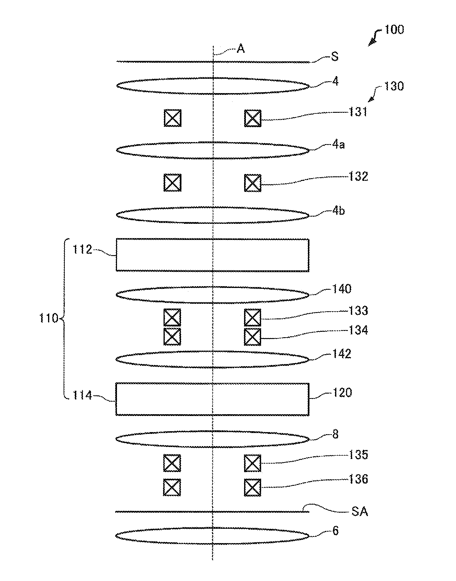
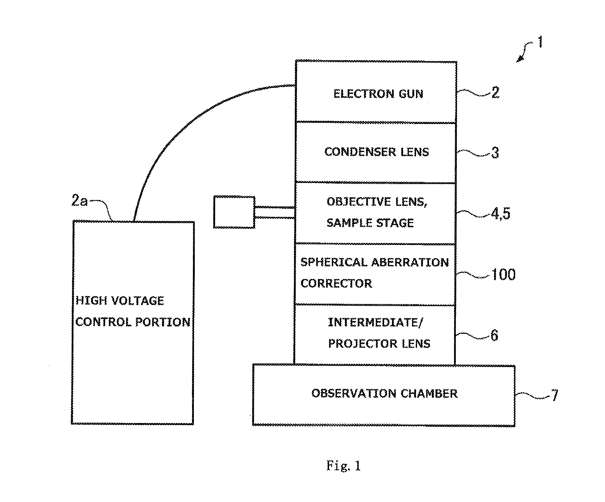
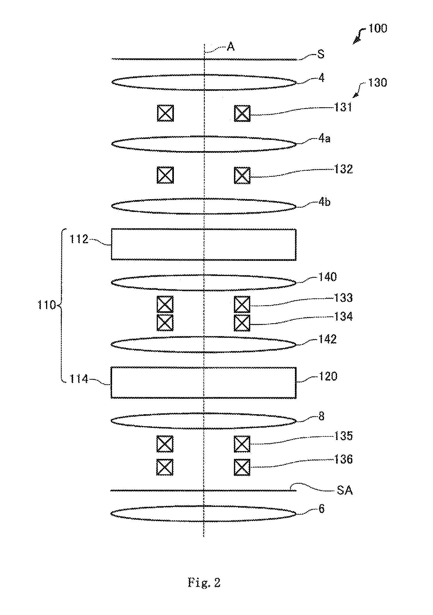
[0066]A spherical aberration corrector associated with a first embodiment of the present invention is first described by referring to FIG. 1, which shows the configuration of a charged particle beam instrument 1 including the spherical aberration corrector, 100.

[0067]The spherical aberration corrector 100 is for use with a charged particle beam instrument that is a microscope for obtaining magnified images and diffraction patterns by directing charged particles such as electrons or ions at a subject under observation. For example, the charged particle beam instrument is a transmission electron microscope (TEM), a scanning transmission electron microscope (STEM), a scanning electron microscope (SEM), or the like. In this example, the charged particle beam instrument 1 is a transmission electron microscope (TEM).

[0068]As shown in FIG. 1, the charged particle beam instrument 1 includes the spherical aberration corrector 100 that ope...

experimental example

1.3. Experimental Example

[0126]In the present experimental example, deviation of the circularity of a diffraction pattern was corrected using the charged particle beam instrument 1 equipped with the spherical aberration corrector 100 associated with the first embodiment. Polycrystalline gold was used as a sample.

[0127]FIG. 9 shows a diffraction pattern (Debye ring) obtained from the polycrystalline gold before the deviation of the circularity of a diffraction pattern was corrected. FIG. 10 shows a diffraction pattern (Debye ring) obtained from the polycrystalline gold after correcting the deviation of the circularity of the diffraction pattern.

[0128]Before the deviation of the circularity of the pattern diffraction is corrected, a Debye ring corresponding to each crystalline plane is elliptical as shown in FIG. 9. After the deviation of the circularity of the diffraction pattern has been corrected, the Debye ring corresponding to individual crystalline planes is closer to a true cir...

second embodiment

2. Second Embodiment

2.1. Spherical Aberration Corrector

[0134]A spherical aberration corrector associated with a second embodiment of the present invention is next described by referring to FIG. 12, which shows the optical system of the spherical aberration corrector, 300, associated with the second embodiment.

[0135]Those components of the spherical aberration corrector 300 associated with the second embodiment which are similar in function with their respective counterparts of the spherical aberration corrector 100 associated with the first embodiment are indicated by the same reference numerals as in the above-cited figures and a description thereof is omitted.

[0136]As shown in FIG. 2, the above-described spherical aberration corrector 100 has the octopole field superimposing portion 120. This octopole field superimposing portion 120 superimposes an octopole field on a hexapole field. The deflection portion 130 deflects the electron beam. Induced four-fold astigmatism is corrected....


PUM


Abstract

A spherical aberration corrector is offered which permits a correction of deviation of the circularity of at least one of an image and a diffraction pattern and a correction of on-axis aberrations to be carried out independently. The spherical aberration corrector (100) is for use with a charged particle beam instrument (1) for obtaining the image and the diffraction pattern and has a hexapole field generating portion (110) for producing plural stages of hexapole fields, an octopole field superimposing portion (120) for superimposing an octopole on at least one of the plural stages of hexapole fields to correct deviation of the circularity of at least one of the image and diffraction pattern, and a deflection portion (130) for deflecting a charged particle beam.

Description

BACKGROUND OF THE INVENTION[0001]1. Field of the Invention[0002]The present invention relates to a spherical aberration corrector, method of spherical aberration correction, and charged particle beam instrument.[0003]2. Description of Related Art[0004]Spherical aberration correctors of the two stage three-fold-field type, i.e., using thick fields having three-fold symmetry (that is, using three-fold symmetric fields having a thickness along the optical axis), are used as spherical aberration correctors in electron microscopes such as transmission electron microscopes (TEM) and scanning transmission electron microscopes (STEM).[0005]It is known that, if two-fold astigmatism is induced at an optically different plane, a deviation of the circularity of an image (deviation in aspect ratio) or a deviation of the circularity of a diffraction pattern occurs (see, for example, O. Scherzer, Optik 2 (1947), 114).[0006]The spherical aberration corrector of the two stage three-fold-field type u...

Claims


Application Information

Patent Timeline
Patent Type & Authority Applications(United States)
IPC IPC(8): G02B27/00
CPCG02B27/0037G01N23/20G02B27/42G02B27/4205G21K1/08H01J3/04H01J3/12H01J3/26H01J37/05H01J37/147H01J37/1472H01J37/153H01J37/28H01J2237/1532H01J2237/1534
Inventor SAWADA, HIDETAKAJIMBO, YU
Owner JEOL LTD
Why Eureka
Try Eureka