Using micro optical elements for depth perception in luminescent figurative structures illuminated by point sources

a technology of luminescent figurative structures and micro optical elements, applied in the field of lighting units, can solve the problems of complex construction, inconvenient operation, and inconvenient use, and achieve the effects of reducing the total height of the assembly, reducing the thickness or width of the lighting unit, and increasing the optical efficiency of the assembly

Inactive Publication Date: 2015-02-12
KONINKLJIJKE PHILIPS NV
View PDF4 Cites 0 Cited by
  • Summary
  • Abstract
  • Description
  • Claims
  • Application Information

AI Technical Summary

Benefits of technology

[0029]In an embodiment, the light source is configured to illuminate the upstream face in an indirect way. For instance, one or more mirrors may be used to reflect the light of the light sources in the direction of the optical plate (i.e. its upstream face). Such embodiments may be used to decrease the thickness or width of the lighting unit. Hence, in order to further lower the total height of the assembly one can apply one or more specular mirrors. In this manner the distance of for instance about 25 cm is created virtually. Optionally, a curvature in the specular reflector may help to increase the optical efficiency of the assembly as rays normal to the optical plate have higher transmission efficiency.
[0030]Further, it appears advantageous to apply

Problems solved by technology

Prior art systems often suffer from a substantial

Method used


Image

  • Using micro optical elements for depth perception in luminescent figurative structures illuminated by point sources
  • Using micro optical elements for depth perception in luminescent figurative structures illuminated by point sources
  • Using micro optical elements for depth perception in luminescent figurative structures illuminated by point sources

Examples


Embodiment Construction

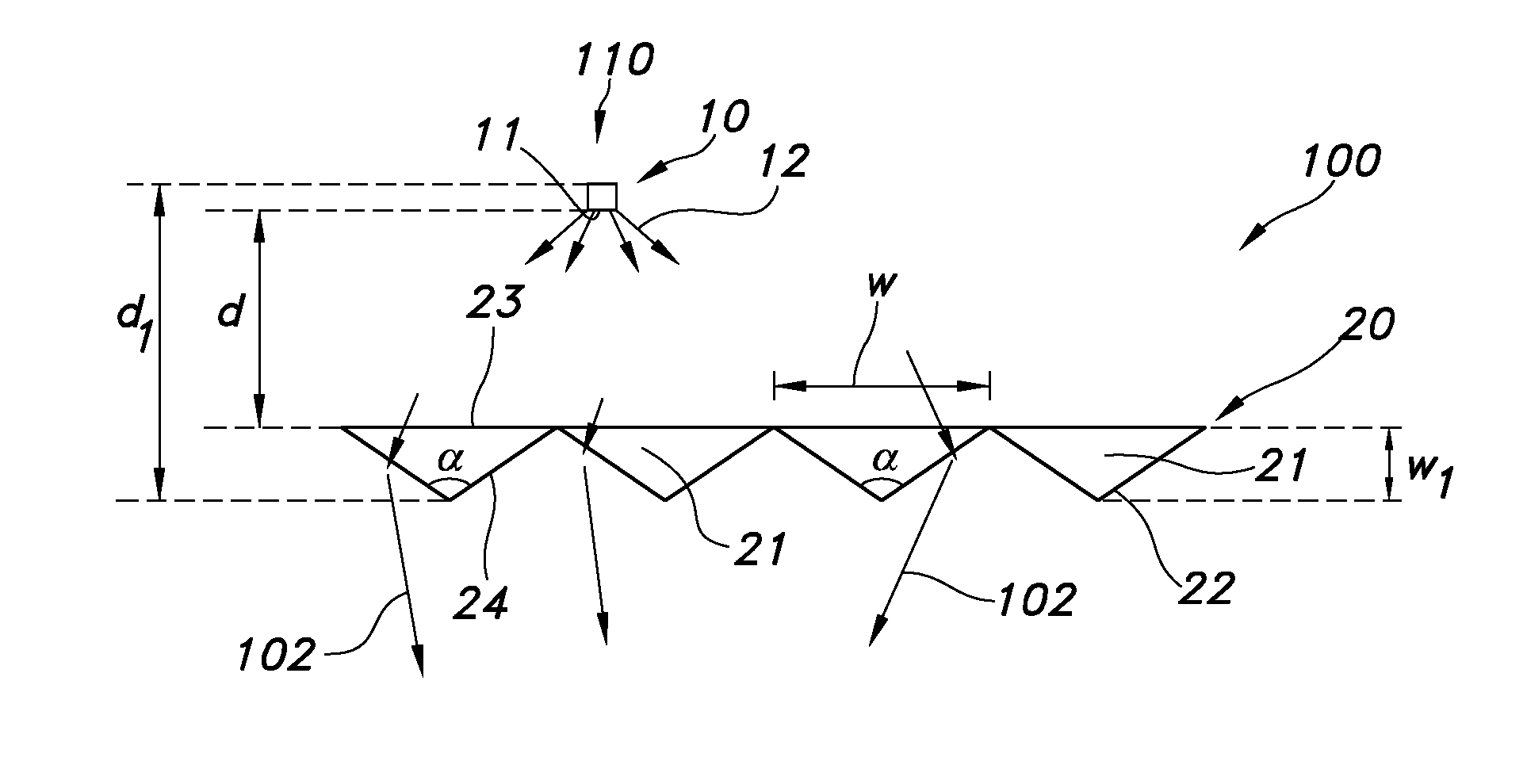
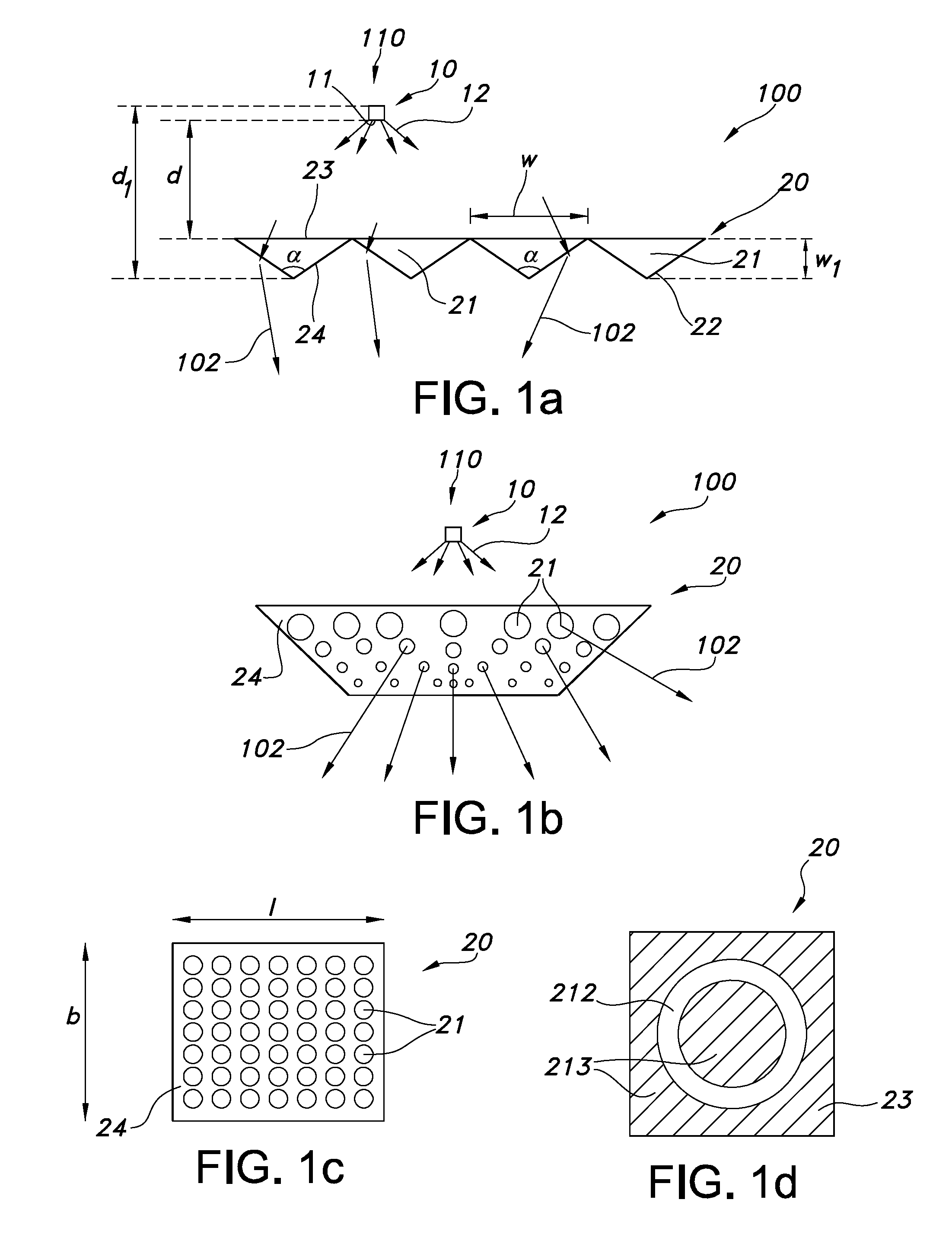
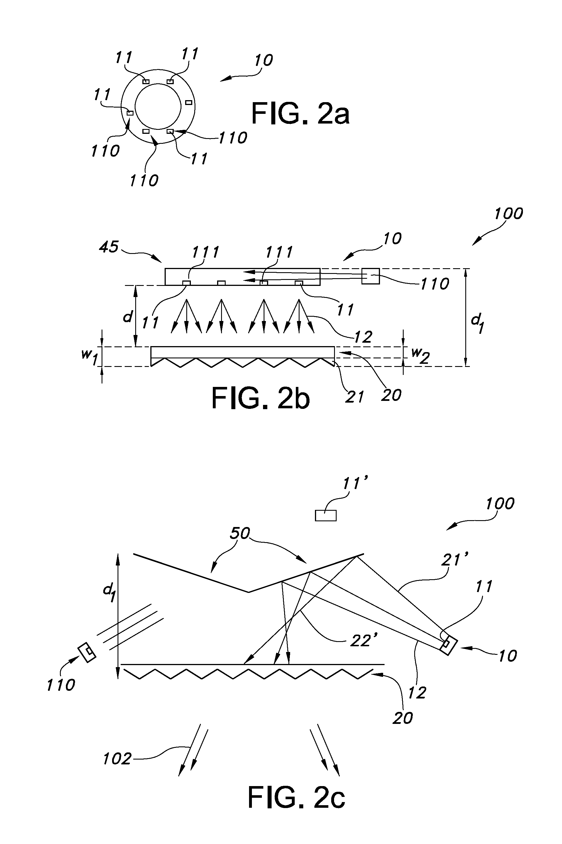
[0043]FIG. 1a schematically depicts lighting unit 100. The lighting unit 100 comprises a light source 10 and a transmissive optical plate 20. The light source 10 comprises a light exit surface 11 for light source light 12. In general, the light source will comprise a plurality of light sources and / or a plurality of light exit surfaces 11 (see also FIGS. 2a-2c).

[0044]The transmissive optical plate 20 comprises an upstream face 23 directed to the light exit surface 11 of the light source 10 and a downstream face 24 facing away from the light exit surface 11 of the light source. The upstream face 23 is downstream of the light source 10, but upstream of the downstream face 24; the downstream face 24 is downstream of the upstream face 23 and downstream of the light source 10. Light 12 of the light source 10 is transmitted through the optical plate 20 in a direction from the upstream face 23 to the downstream face 24. Light escaping from the downstream face 24 is indicated as lighting uni...


PUM


Abstract

The invention provides a lighting unit comprising a light source and a transmissive optical plate, wherein the light source comprises a light exit surface for light source light, wherein the transmissive optical plate comprises an upstream face directed to the light exit surface of the light source and a downstream face arranged away from the light exit surface) of the light source, wherein the optical plate comprises a 2D array of micro optical elements for refraction of the light source light in a direction away of the downstream face, wherein the geometrical path length from the light exit surface to the transmissive optical plate is at least 20 cm.

Description

FIELD OF THE INVENTION[0001]The invention relates to a lighting unit comprising a light source and an optical plate as well as to the use of such lighting unit.BACKGROUND OF THE INVENTION[0002]The production of 3D images with light is known in the art. WO / 2005 / 117458, for instance, describes an apparatus and method for displaying 3D images. The apparatus comprises: a) a screen with angular dependent diffusion characteristics for direction selectively forwarding light; b) a screen illuminating system, the screen illuminating system comprising multiple modules for generating multiple light beams incident on points of the screen, the modules being arranged so that each point of the screen is illuminated by multiple modules, and the incident light beams generated by one module are projected into multiple different directions from the module towards multiple different points of the screen, and further the different incident light beams generated by one module are forwarded towards differ...

Claims


Application Information

Patent Timeline
IPC IPC(8): F21V5/00G02B27/22G02B27/30
CPCF21V5/002F21Y2101/02G02B27/22G02B27/30F21Y2115/10G02B5/0215G02B5/0278G02B5/0294G02B27/095
Inventor GOMMANS, HENDRIKUS HUBERTUS PETRUS
Owner KONINKLJIJKE PHILIPS NV
Why Eureka
Try Eureka