Efficient control and stall prevention in advanced configuration aircraft

a technology of advanced configuration and stall prevention, applied in the field of aircraft, can solve the problems of unfavorable separation of wing airflow, superficial resemblance, and observed fundamental flaws, and achieve the effects of reducing the number of parts, low cost, and high performan

Active Publication Date: 2015-02-19
DBT AERO INC
View PDF2 Cites 21 Cited by
  • Summary
  • Abstract
  • Description
  • Claims
  • Application Information

AI Technical Summary

Benefits of technology

[0024]Improvements to aircraft design succeed only when safety is preserved and value is maintained relative to prior art. The present invention applies the method for stall prevention previously disclosed, in a form having inherently strong wings (2,4), in which simplicity and reduced parts count are driving principles. The result for the novel invention herein disclosed is the introduction of yet higher performance at low cost. For example, the absence of wing ailerons in a preferred embodiment (FIG. 2), has provided new opportunity for low cost implementation of a method of boundary layer control shown to be preferred.
[0025]Use of suction for boundary laye

Problems solved by technology

In the prior art, operating the ailerons to produce force opposite to wing lift causes an undesirable separation of wing airflow.
However, any resemblance is superficial.
As a result, a fundamental flaw has been obser

Method used


Image

  • Efficient control and stall prevention in advanced configuration aircraft
  • Efficient control and stall prevention in advanced configuration aircraft
  • Efficient control and stall prevention in advanced configuration aircraft

Examples


Embodiment Construction

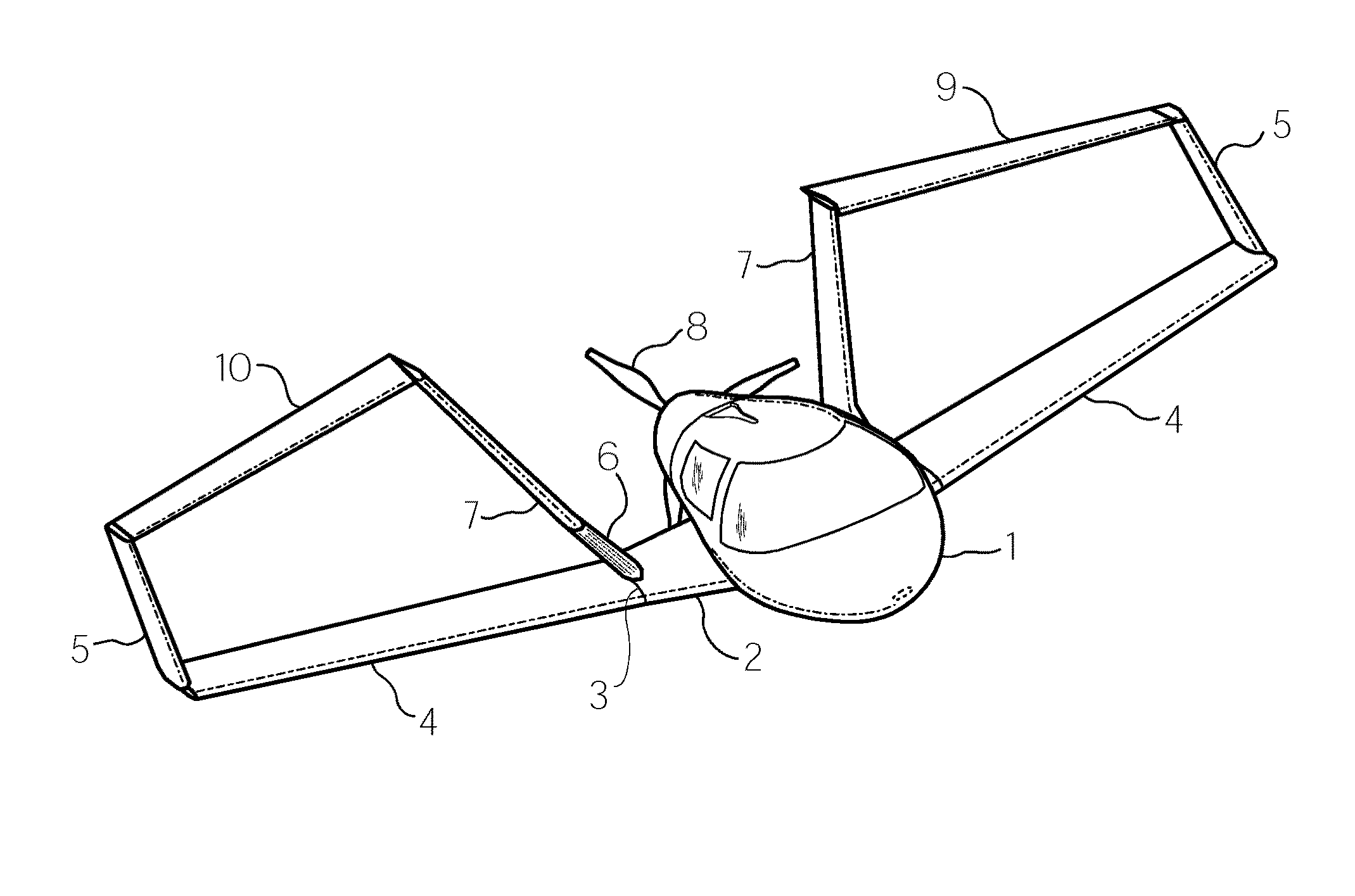
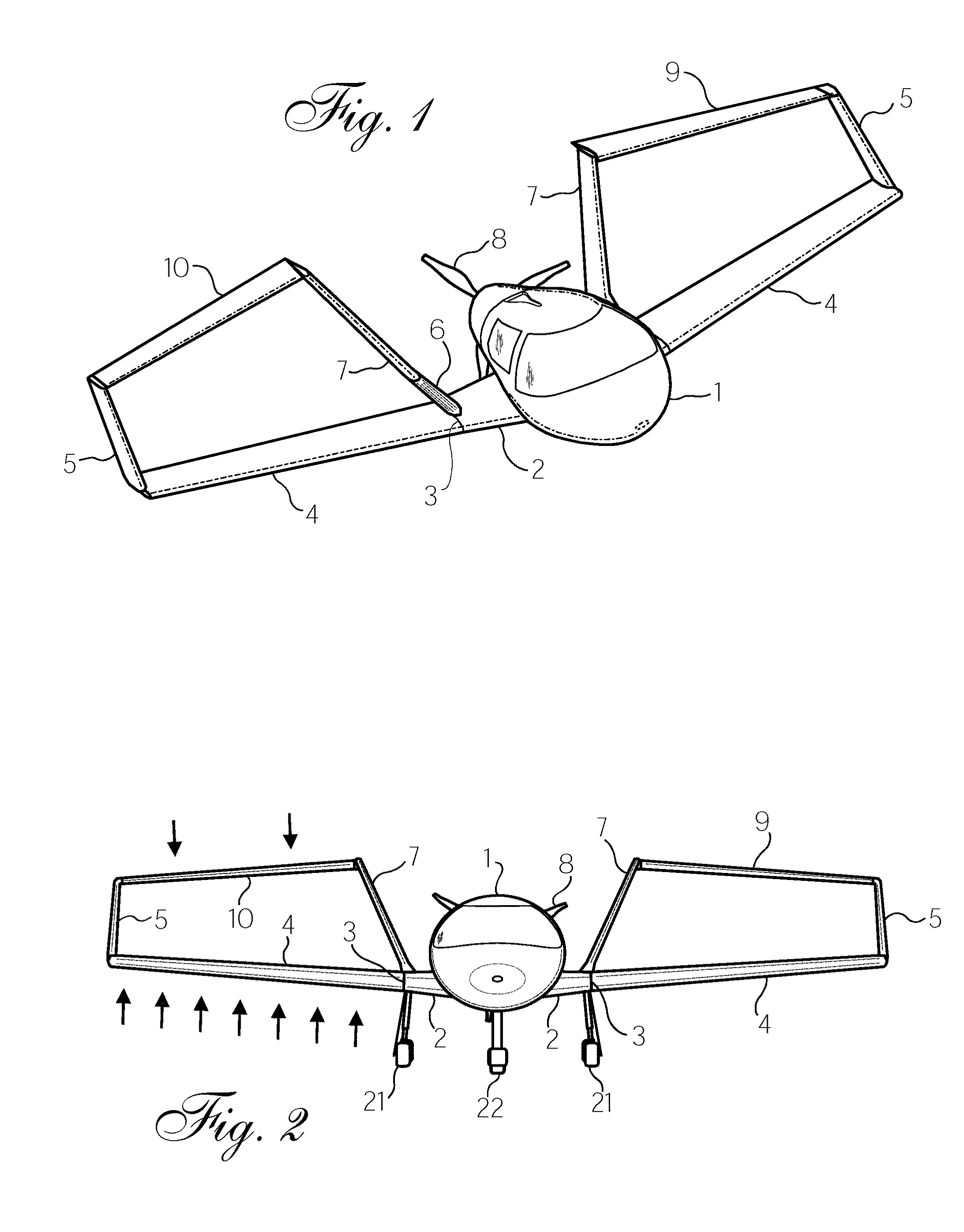
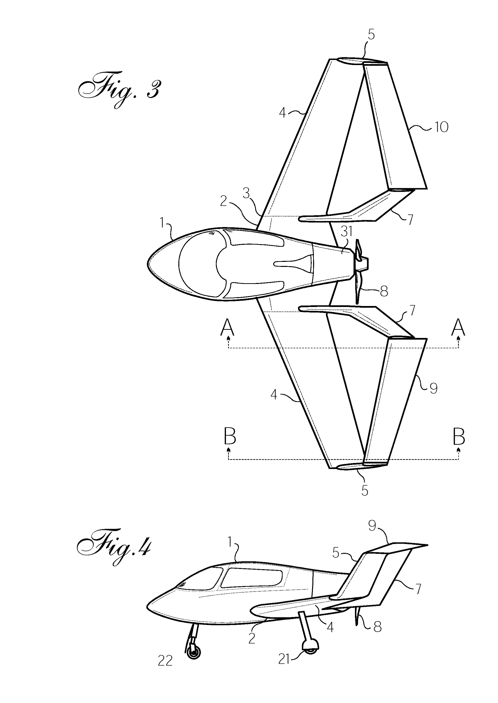
[0060]The invention disclosed is a fundamental enabling technology that may be embodied in various forms. Therefore, specific details disclosed herein are not to be interpreted as limiting, but rather as a basis for the claims and as a representative basis for teaching one skilled in the art to employ the present invention in virtually any appropriately detailed system, structure, or manner. The present invention applies to innumerable aircraft designs including next (FIG. 5) and future generation (FIG. 13) large transport aircraft, next generation general aviation aircraft (FIG. 1), commuter aircraft (FIG. 16), blended wing body aircraft (FIG. 17), Light Sport Aircraft (FIG. 15), personal air vehicles, remotely piloted vehicles (RPVs), unmanned aerial vehicles (UAVs), model aircraft, toy airplanes, and many others. Since the invention can be readily adapted into products built by a majority of aircraft manufacturers, using a variety of material processes, the technology is not disr...


PUM


Abstract

An apparatus forming an aircraft which is designed for flight by movement through the air, the aircraft has a front and rear portions and a center of mass, with left and right sides when divided by a central plane of reference. The aircraft has inboard portions closer to said central plane of reference and outboard portions farther from said central plane of reference. Further, the aircraft contains at least one positive lifting aerodynamic surface configured to affect the flow of air near said at least one positive lifting aerodynamic surface when said aircraft is appropriately moving forward, and at least one elevon structure configured to create negative aerodynamic force when said aircraft is appropriately moving forward. The elevon structure is constructed so as to have outboard portions thereof positioned outward of said central plane of reference to a distance at least three-fourths of the distance from said central plane of reference to a tip end of said at least one wing.

Description

CROSS-REFERENCE[0001]This application claims the benefit of priority from U.S. Provisional Application No. 61 / 640,607, filed Apr. 30, 2012, and is a continuation-in-part of U.S. application Ser. No. 11 / 623,042, filed Jan. 12, 2007.FIELD OF THE INVENTION[0002]This invention relates to the field of aircraft; specifically to powered and unpowered aircraft of all sizes, especially those operable at high levels of aerodynamic efficiency; whether manned or unmanned; controlled or uncontrolled. The invention applies generally to design in fluid dynamic disciplines.BACKGROUND OF THE INVENTION[0003]Modern aircraft design recognizes conflicting priorities between higher speed and lower speed operations. Aircraft for low speed flight differ markedly from those intended for high speed flight, and one type may rarely be useful for the other. Historically, to obtain higher speed requires higher power, and high powered aircraft use a lot of fuel. Fast aircraft generally require long paved runways....

Claims


Application Information

Patent Timeline
IPC IPC(8): B64C9/00
CPCB64C2009/005B64C9/00B64C3/16B64C31/02B64C39/068B64C39/08B64C23/069Y02T50/10Y02T50/30Y02T50/40
Inventor MCGINNIS, JOHN WILLIAM
Owner DBT AERO INC
Why Eureka
Try Eureka