Vehicle control system

a technology of vehicle control and control system, which is applied in the direction of machine/engine, process and machine control, instruments, etc., can solve the problems of consuming electric power of electric oil pump, mechanical oil pump cannot cool the electric rotary machine or similar component, and so as to improve economic efficiency of electric power and ensure long service life of electric coolant pump.

Active Publication Date: 2015-02-19
TOYOTA JIDOSHA KK +2
View PDF6 Cites 15 Cited by
  • Summary
  • Abstract
  • Description
  • Claims
  • Application Information

AI Technical Summary

Benefits of technology

[0024]In the vehicle control system, if the control unit is configured to set the hysteresis characteristic for determination as to whether to operate the electric coolant pump, repeat of operation start and operation stop of the electric coolant pump in a short time is prevented, so that long service life of the electric coolant pump is ensured.
[0025]In the vehicle control system, if the control unit is configured to set the operation threshold temperature and the stop threshold temperature such that a difference between the operation threshold temperature and the stop threshold temperature takes at least two different values, one of which is a first temperature difference corresponding to a first output value, which is a value of the output of the electric rotary machine, the other of which is a second temperature difference corresponding to a second output value, which is a value of the output of the electric rotary machine and is larger than the first output value, and the second temperature difference is greater than the first temperature difference, in the case where the output of the electric rotary machine is large, the period of time, during which the electric coolant pump is operated, is set long to sufficiently cool the electric rotary machine, and on the other hand, in the case where the output of the electric rotary machine is small, the

Problems solved by technology

In the case where an electric oil pump is provided together with a mechanical oil pump directly coupled to a crankshaft of an engine, driving only the electric oil pump over long period accelerates its deterioration.
However, when the engine stops, the mechanical oil pump cannot cool the electric rotary machine or similar component.
However, the electric o

Method used


Image

  • Vehicle control system
  • Vehicle control system
  • Vehicle control system

Examples


Embodiment Construction

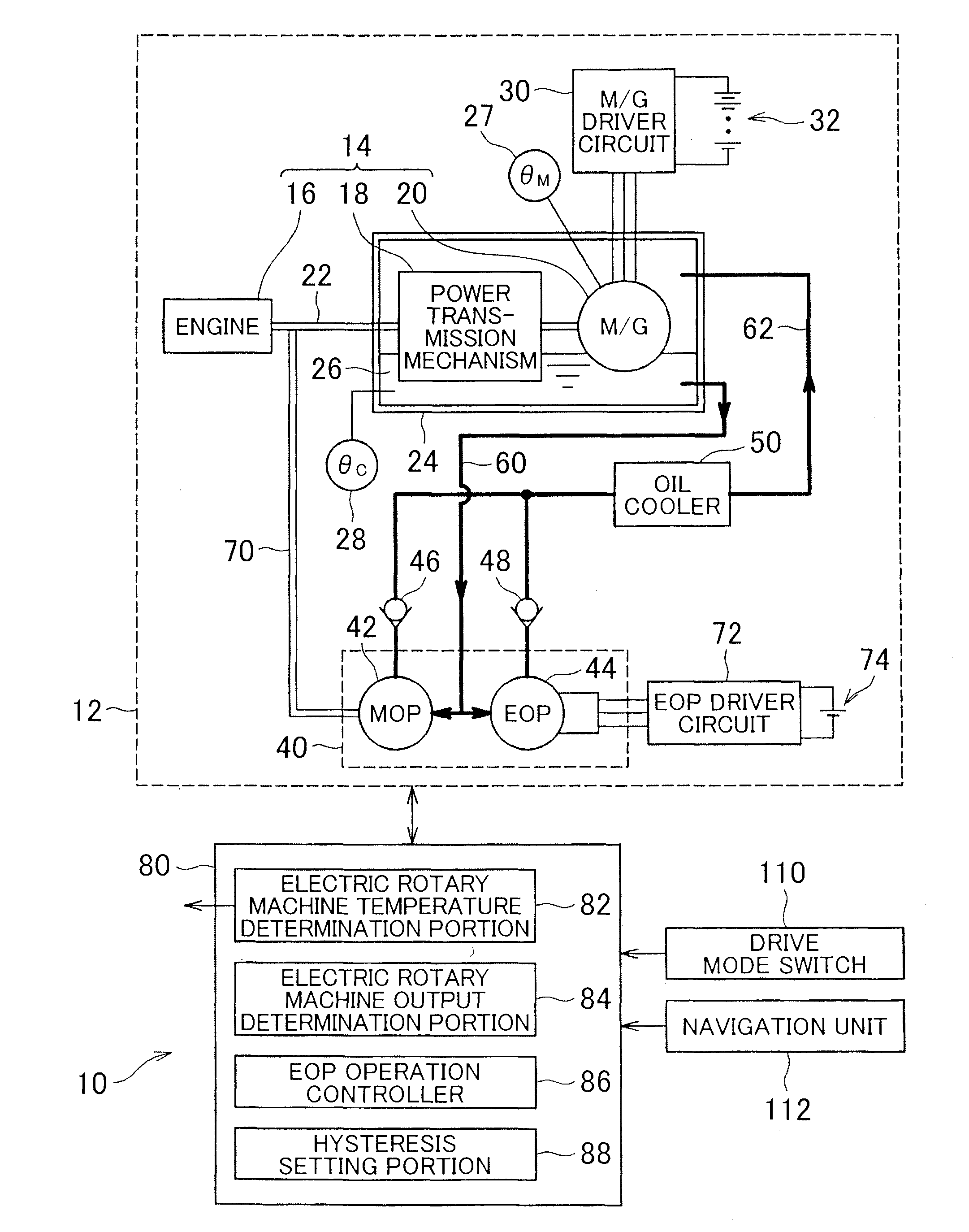
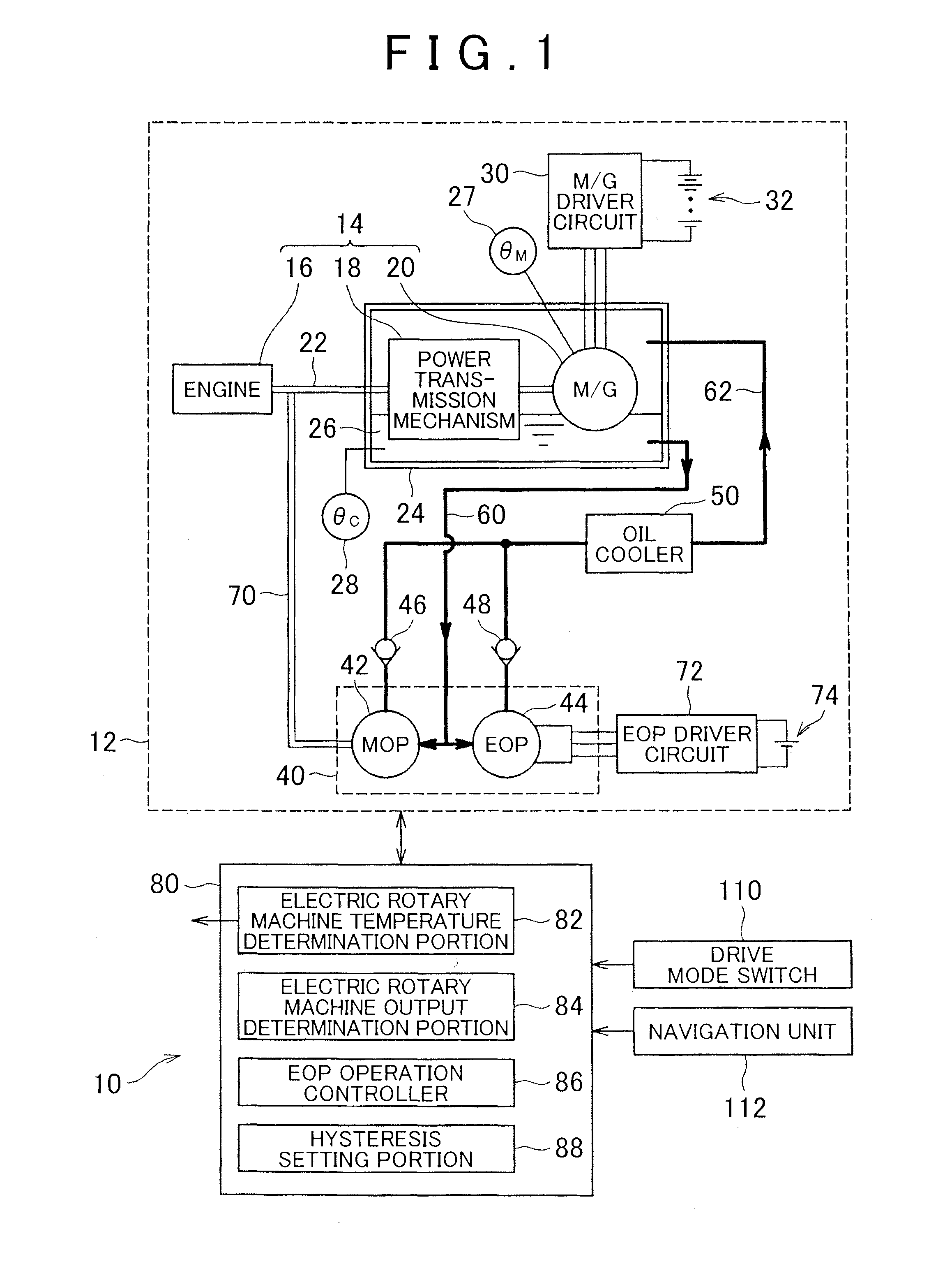
[0037]A detailed description will be given of an embodiment according to the invention with reference to the attached drawings. The following describes a hybrid vehicle with an engine and an electric rotary machine as a vehicle. However, this is an example for explanation. Any configuration is possible as long as the vehicle includes an electric rotary machine. For example, an electric vehicle without an engine may be employed. As a power unit of the hybrid vehicle, a configuration including an engine, one electric rotary machine, and a power transmission mechanism provided between the engine and the one electric rotary machine will be described. This is also an example for explanation. Here, as a hybrid vehicle, any configuration is possible as long as the hybrid vehicle has the engine and the electric rotary machine. The relationship between an output of the engine and an output of the electric rotary machine can be changed according to specifications of the vehicle as necessary. ...


PUM


Abstract

A vehicle control system includes: a power unit including an electric rotary machine; an electric coolant pump configured to circulate a coolant that cools the electric rotary machine; and a control unit configured to operate the electric coolant pump based on a condition that a temperature of the electric rotary machine is equal to or higher than a predetermined operation threshold temperature, and a condition that an output of the electric rotary machine is equal to or higher than a predetermined operation threshold output.

Description

BACKGROUND OF THE INVENTION[0001]1. Field of the Invention[0002]The invention relates to a vehicle control system. In particular, the invention relates to a vehicle control system, in which an electric rotary machine can be cooled with an electric coolant pump.[0003]2. Description of Related Art[0004]For a vehicle with an engine and an electric rotary machine, an oil pump referred to as an electric oil pump or an electrically-driven oil pump is employed as well as a mechanical oil pump, which is driven by the engine, to cool the electric rotary machine, an automatic transmission, or similar component. The electric oil pump and the electrically-driven oil pump are driven with a battery or similar member even when an engine stops.[0005]For example, Japanese Patent Application Publication No. 2011-106296 (JP 2011-106296 A) discloses a vehicle that includes a mechanical oil pump and an electric oil pump and controls automatic stop of the engine according to a driving state of the electr...

Claims


Application Information

Patent Timeline
IPC IPC(8): B60W20/00F01P7/14
CPCB60W20/00F01P7/14Y10S903/904F01P2070/10F01P2023/08B60K6/26B60W30/1843F16H57/0476B60W2510/087B60W2510/085F16H2061/0037F16H61/0031
Inventor MIYAMOTO, TOMOHIKOYAGI, NORIYUKIMATSUMURA, SHIGERUNAGATA, KENJIROSUGIMOTO, MASATOSHI
Owner TOYOTA JIDOSHA KK
Why Eureka
Try Eureka