Eureka AIR delivers breakthrough ideas for toughest innovation challenges, trusted by R&D personnel around the world.

Three-phase power supply and system of leds with three-phase power supply

a power supply and three-phase technology, applied in the direction of ac-dc conversion, electrical apparatus, efficient power electronics conversion, etc., can solve the problems of power loss converted into heat, and the electrical system of fluorescent lamps is susceptible to overvoltage, so as to achieve the effect of reducing the loss of power converted into the hos

Active Publication Date: 2015-02-26
MILOO ELECTRONICS
View PDF4 Cites 10 Cited by
  • Summary
  • Abstract
  • Description
  • Claims
  • Application Information

AI Technical Summary

Benefits of technology

The invention provides a three-phase power supply with a system of high emitting diodes (LEDs) that reduces power loss compared to existing power supplies. The power supply has a full-wave rectifier with two diodes connected in series for each phase, connected to a wire voltage line. The cathode of one diode is connected to the power supply of the LED system, and the anode of the other diode is connected to the power supply of an electronic device equipped with a control arrangement. The full-wave rectifier diodes are connected in parallel with a conductive field-effect transistor (FET) to save electrical energy. Metal shielding layers and layers with electrical circuits connected to the LED system and a system to protect against damage from electrostatic discharges are placed on the circuit board. The technical effect is to reduce power loss and improve efficiency in providing power to LED systems.

Problems solved by technology

A disadvantage of the known solutions is a problem with losses of power converted into heat which must be discharged outside LEDs systems and a susceptibility to overvoltage of fluorescent lamp electrical system.

Method used


Image

  • Three-phase power supply and system of leds with three-phase power supply
  • Three-phase power supply and system of leds with three-phase power supply
  • Three-phase power supply and system of leds with three-phase power supply

Examples


Embodiment Construction

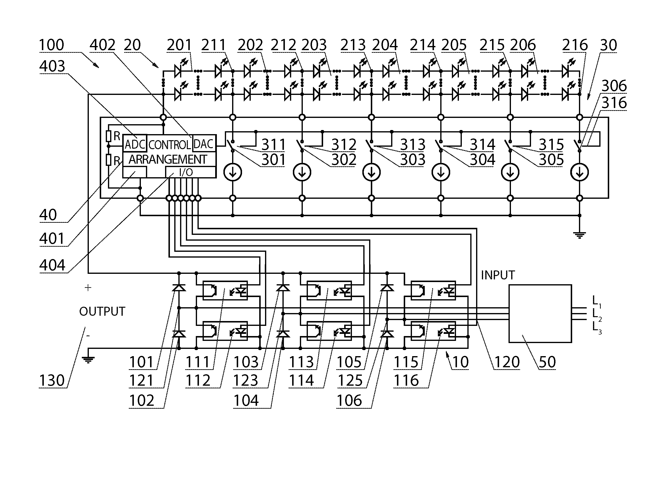
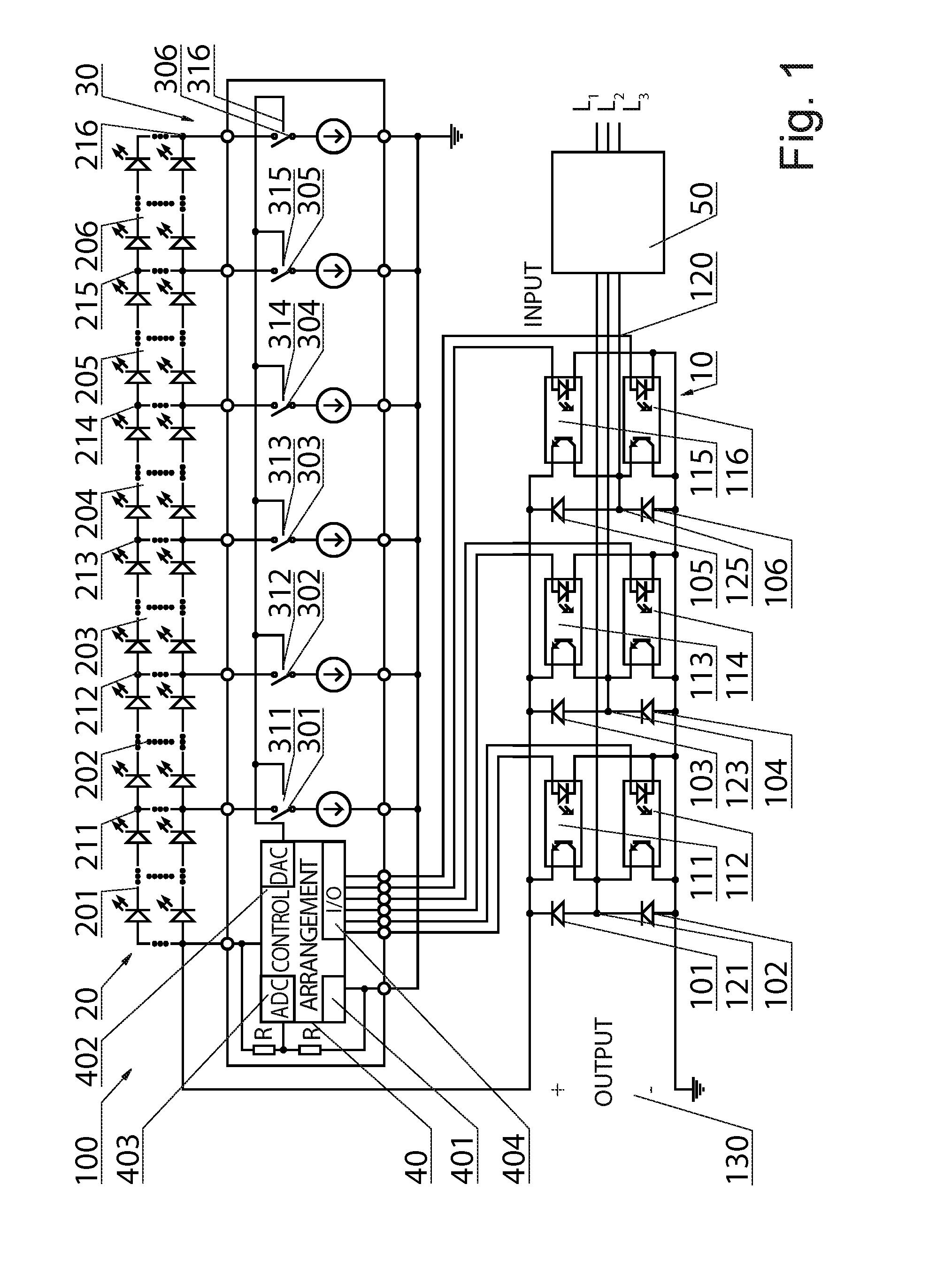
[0031]A three-phase power supply 10 or power supply system with an input 120 and an output 130 being a part of an electrical system 100, presented in FIG. 1 and intended especially to supply LEDs system 20, is a system of a diode six half-wave rectifier which comprises rectifier diodes 101, 102, 103, 104, 105, 106. If a linear LED sequencer is used to build a high-power lighting system, for example over 1 kW, power losses in a passive rectifying diode can achieve significant values in the embodiment shown in FIG. 1, version of an active diode rectifier additionally equipped with FETs is presented. The six rectifying diodes 101, 102, 103, 104, 105, 106 form three pairs 101 and 102, 103 and 104, 105 and 106 of two rectifying diodes connected in series at a connection point 121, 123, 125. One pair of two rectifying diodes is associated with one phase of the three-phase alternating current (AC) power supply connected to the connection point 121, 123, 125. wherein each cathode of one 101...


PUM


Abstract

A three-phase power supply (10), intended especially to supply LEDs system (20), has a system of a diode bridge rectifier which comprises rectifying diodes (101, 102, 103, 104, 105, 106). The three-phase power supply (10) is additionally equipped with FETs and each of the rectifying diodes is bypassed by an FET of a rectifying unit (111, 112, 113, 114, 115, 116), respectively, which is controlled by a control system (40), comprising en anglogue-to-digital converter ADC 403, a digital-to-analogue converter (402), a microcontroller (401), which provides a control signal to a gate of the appropriate FET through the input / output (404). Once the control system (40), in particular the microcontroller (401), detects stable power supply conditions and starts operation of elements of an LED sequencer (30), it starts at the same time to control over the FETs in the active rectifier.

Description

CROSS-REFERENCE TO RELATED APPLICATIONS[0001]Pursuant to 35 U.S.C 119 and the Paris Convention Treaty this application claims the benefit of Polish Patent Application No. P405128 filed on Aug. 23, 2013, the contents of which are incorporated herein by reference.BACKGROUND OF THE INVENTION[0002]1. Field of the Invention[0003]Technical concept presented herein relates to a three-phase power supply and a system of light emitting diodes (LEDs) with the three-phase power supply, especially a system of LEDs for illuminating devices.[0004]2. Description of the Related Art[0005]The growing demand for energy, including electric energy, forces the use of new cost-effective solutions, including in the area of illuminating rooms, which are characterised by low power loss and high luminous efficiency, and the most well-known of these use LEDs, whose luminous efficiency exceeds even 100 lm / W, as a light source.[0006]International application WO 2011014450 A titled “Three-phase led power supply” d...

Claims


Application Information

Patent Timeline
IPC IPC(8): H05B33/08H02M1/00H02M1/36H05B44/00
CPCH05B33/0809H02M1/36H02M7/219H05B45/48Y02B20/30Y02B70/10H05B45/3725H02M1/0048H02M7/2195H02M1/32
Inventor WLODARCZYK, MILOSZKOLASZEWSKI, LUKASZBRZEGOWY, RAFAL
Owner MILOO ELECTRONICS
Why Eureka
Eureka Blog
Learn More