

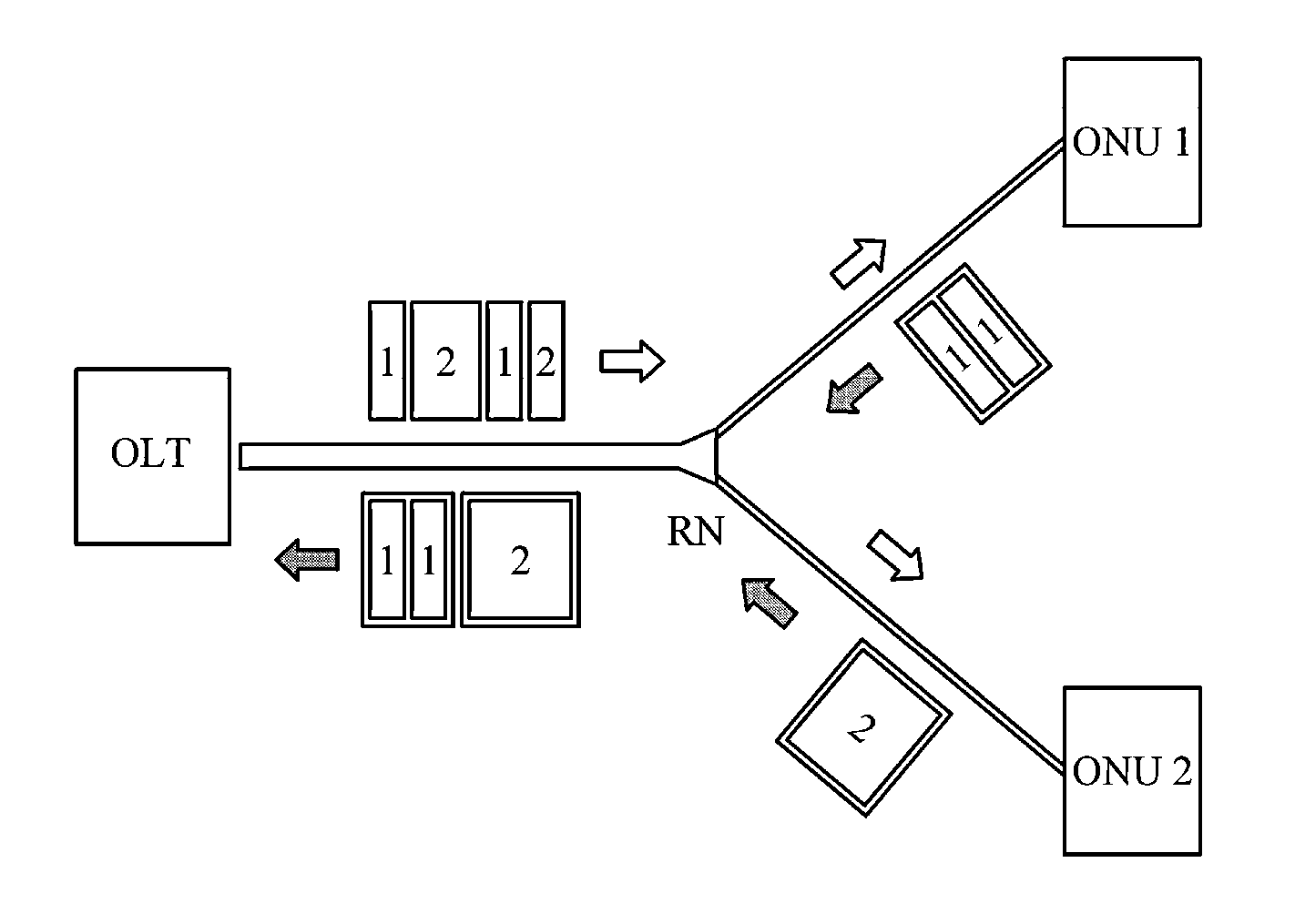
Passive optical network system using time division multiplexing
a technology of time division multiplexing and optical network, applied in the field of passive optical network using time division multiplexing mechanism, can solve the problems of inability to completely prevent a current incoming to a light source, disadvantageous decrease of the transmission time to be allocated for each subscriber with an increase in the number of operating onus, and relatively long period of time, so as to prevent the quality of the upstream signal
- Summary
- Abstract
- Description
- Claims
- Application Information
AI Technical Summary
Benefits of technology
Problems solved by technology
Method used
Image

Examples
Embodiment Construction
[0042]Exemplary embodiments will now be described more fully hereinafter with reference to the accompanying drawings, in which exemplary embodiments are shown. The present disclosure may, however, be embodied in many different forms and should not be construed as limited to the exemplary embodiments set forth herein. Rather, these exemplary embodiments are provided so that the present disclosure is thorough, and will fully convey the scope of the invention to those skilled in the art.
[0043]Throughout the drawings and the detailed description, unless otherwise described, the same drawing reference numerals are understood to refer to the same elements, features, and structures. The relative size and depiction of these elements may be exaggerated for clarity, illustration, and convenience.
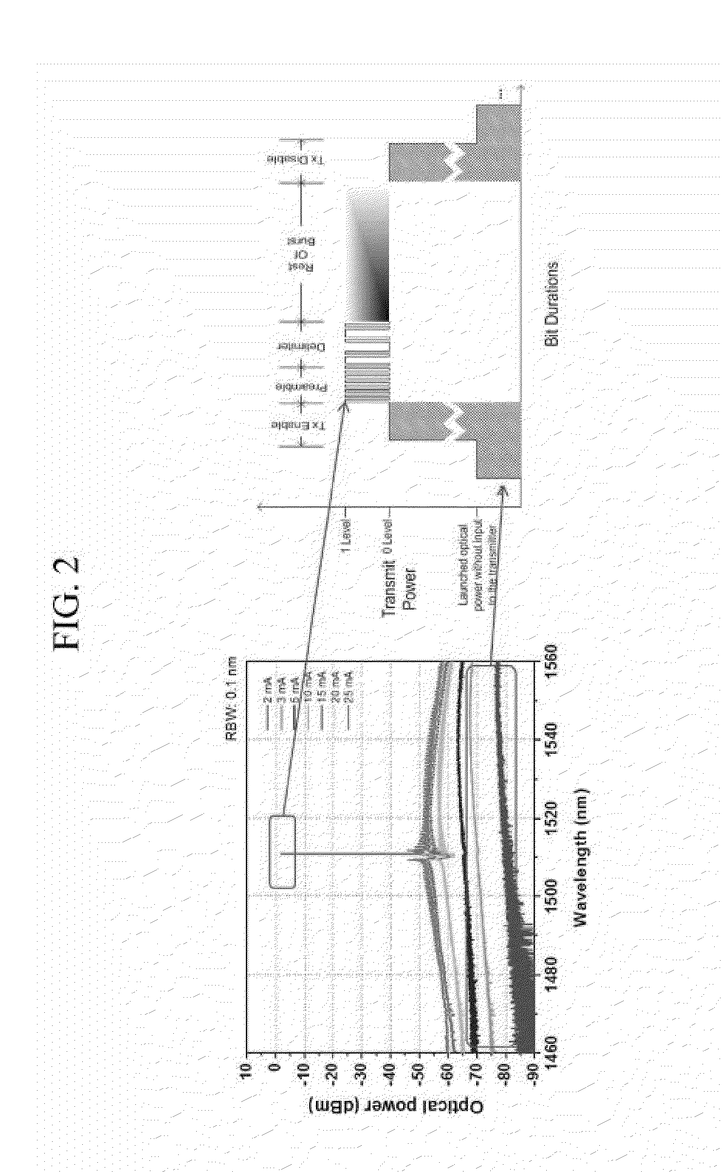
[0044]Prior to description of exemplary embodiments of the present disclosure, penalties on upstream signals that are engendered by a difference between an optical signal power and an optical noise si...
PUM
 Abstract
Description
Claims
Application Information