A Post-Moulding Station and an Associated Method of Manufacture of a Wind Turbine Blade

a manufacturing method and technology of a wind turbine blade, which are applied in the direction of wind energy generation, liquid fuel engine components, non-positive displacement fluid engines, etc., can solve the problems of high-quality blade moulds, blade moulds in use, and considerable cost and lead time in the implementation of a manufacturing process for a new wind turbine blade. achieve the effect of improving the access to different sections of the contained blade shell

Active Publication Date: 2015-02-26
LM WP PATENT HLDG
View PDF16 Cites 11 Cited by
  • Summary
  • Abstract
  • Description
  • Claims
  • Application Information

AI Technical Summary

Benefits of technology

[0145]By providing a rotatable cradle, access to different sections of a contained blade shell may be improved by rotating the cradle and contained shell.

Problems solved by technology

High-quality blade moulds are one of the most expensive pieces of equipment in the blade manufacturing process, requiring extensive tooling and manufacture before use to ensure accurate reproduction of desired blade profiles, as well as to allow for the turning of the moulds to bond blade shell parts together.
Blade moulds in use in current processes can cost approximately ε1-3 million to manufacture and, dependent on where the moulds are made, extensive transportation time may be a factor before a new mould can be used at a manufacturing plant.
This introduces considerable expense and lead time in the implementation of a manufacturing process for a new wind turbine blade.
Accordingly, one of the limitations to efficient implementation of wind turbine technology is the time required for the initial setup of a blade manufacturing system.
A further limitation is the time taken for the manufacturing of individual blades within such a system.
However, the use of such a system will result in an increase in the time required to produce a single wind turbine blade, due to the increase in manufacturing operations involved.

Method used


Image

  • A Post-Moulding Station and an Associated Method of Manufacture of a Wind Turbine Blade
  • A Post-Moulding Station and an Associated Method of Manufacture of a Wind Turbine Blade
  • A Post-Moulding Station and an Associated Method of Manufacture of a Wind Turbine Blade

Examples


Embodiment Construction

[0162]An embodiment of the invention will now be described, by way of example only, with reference to the accompanying drawings, in which:

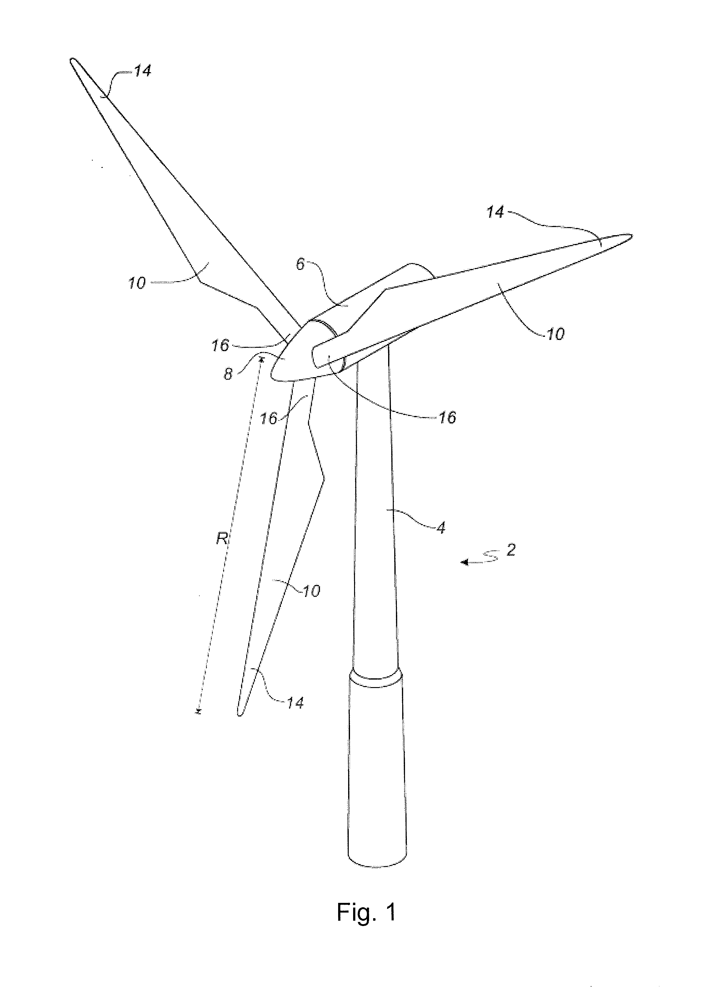
[0163]FIG. 1 shows a wind turbine;

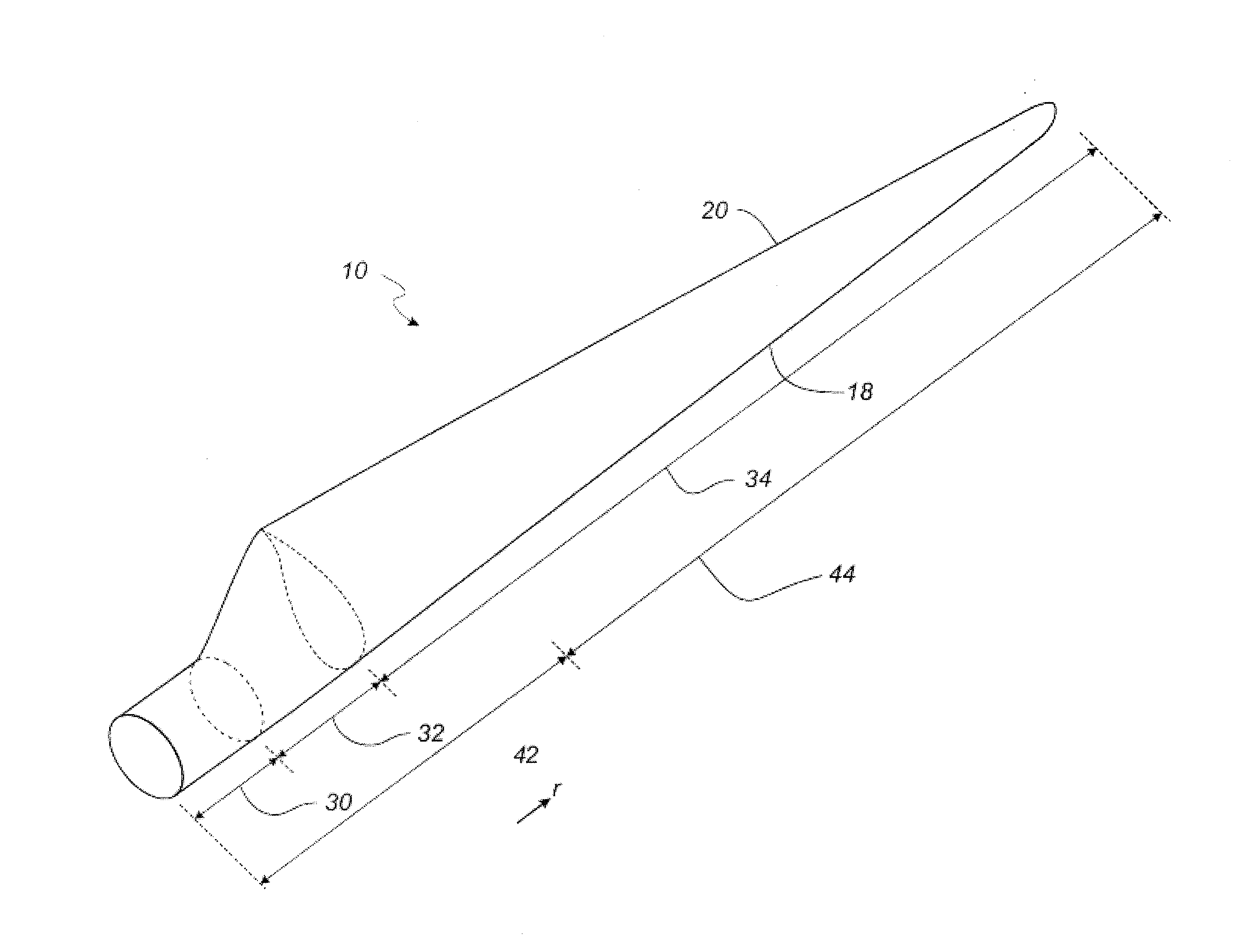
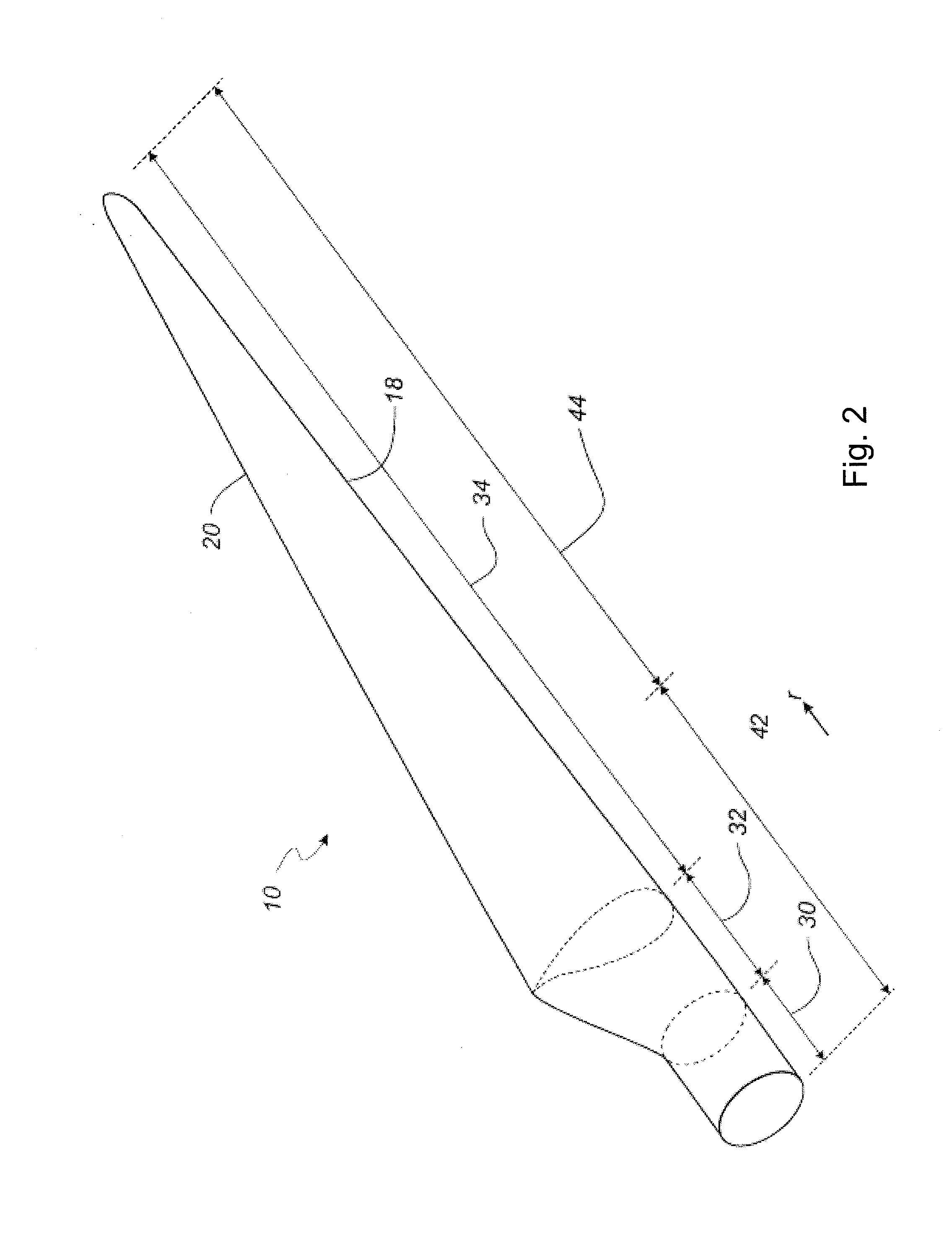
[0164]FIG. 2 shows a schematic view of a wind turbine blade;

[0165]FIG. 3 shows a schematic view of an airfoil profile of the blade of FIG. 2;

[0166]FIG. 4 illustrates an embodiment of a manufacturing process for a wind turbine blade according to the invention;

[0167]FIG. 5 is a top plan view of an embodiment of a post-moulding station for use in the manufacture of a wind turbine blade according to the invention;

[0168]FIG. 6 is a perspective view of the post-moulding station of FIG. 5;

[0169]FIG. 7(a) is a side view of the post-moulding station of FIG. 5 when in an open state;

[0170]FIG. 7(b) is a side view of the post-moulding station of FIG. 5 when in a closed state;

[0171]FIG. 8(a) is an end view of the post-moulding station of FIG. 5 when in an open state;

[0172]FIG. 8(b) is an end view of the post-moulding station o...


PUM

PropertyMeasurementUnit
lengthaaaaaaaaaa
chord lengthaaaaaaaaaa
bonding pressureaaaaaaaaaa

Abstract

A post-moulding station is described which is used in the manufacturing of a wind turbine blade. A blade shell forming part of a wind turbine blade is initially moulded in a blade mould, the blade shell subsequently transferred to a post-moulding station which allows for various post-moulding operations to be carried out on the blade shell away from the mould, thereby increasing the productivity of the blade mould in the manufacturing process. The post-moulding station may be operable to perform the closing of first and second blade shells to form a wind turbine blade, and may be formed from an adjustable structure which can provide relatively easy access to the contained blade shell for working thereon. Accordingly, the manufacturing equipment may be of reduced cost, combined with an increase in the overall productivity of the manufacturing system.

Description

FIELD OF THE INVENTION[0001]The present invention relates to a post-moulding station for use in the manufacture of a wind turbine blade, a method of manufacture of a wind turbine blade using such a post-moulding station, and a manufacturing system for a wind turbine blade including a post-moulding station.BACKGROUND OF THE INVENTION[0002]Wind turbine blades are normally manufactured as first and second blade shells, using a pair of adjacent blade moulds. The blade moulds comprise first and second moulding surfaces conforming to the upwind and downwind halves (or the suction and pressure sides) of a wind turbine blade, the first blade mould used to form a first blade shell and the second blade mould used to form a second blade shell, the shells subsequently joined together to form a wind turbine blade.[0003]A fibrous composite material is initially layered on top of the first and second moulding surfaces, the layers of material conforming to the contours of the moulds to form the ext...

Claims


Application Information

Patent Timeline
Patent Type & Authority Applications(United States)
IPC IPC(8): B29C65/78F01D5/28
CPCB29C65/78F01D5/282B29L2031/08B29K2105/253B29C65/7847B29C65/48B29C65/7802B29C65/7841B29C66/1142B29C66/54B29L2031/085B29C31/00Y10T156/1744Y02E10/72Y02P70/50
Inventor DE WAAL MALEFIJT, BERNARD WILLEM
Owner LM WP PATENT HLDG
Why Eureka
Try Eureka