
Efficient dynamic stimulation in an implanted device

a dynamic stimulation and implanted device technology, applied in the field of electric pulse generators, can solve the problems of artificial stimulation being less natural, side effects, and large fiber stimulation, and achieve the effect of reducing current leakage from the cuff and improving electrical sealing

Inactive Publication Date: 2015-02-26
MEDTRONIC INC
View PDF2 Cites 2 Cited by
  • Summary
  • Abstract
  • Description
  • Claims
  • Application Information

AI Technical Summary

Benefits of technology

The invention aims to reduce or eliminate a type of electrical breakage called anodal break excitation. It does this by using a strip of metal foil with curved end portions that are embedded in insulating material. This securely fixes the electrode to the insulating material of a cuff and helps prevent breakage. The curved portions have a small radius of curvature, which ensures a tight fit between the electrode and the insulating material. Overall, this invention improves the reliability and durability of the electrical connection.

Problems solved by technology

Such excitation is typically an undesired side effect of the tissue stimulation, and methods to reduce or eliminate the effect have been sought.
The loss of these properties causes the effect of artificial stimulation to be less natural, and may result in side effects, because axons in the bundle in addition to the target axon are indiscriminately activated.
In addition, stimulation of large fibers can cause unwanted side effects (see, for example, Rijkhoff et al.
This unnatural recruitment order causes muscle fatigue and poor force gradation.
This long pulse may degrade stimulation efficiency.
The main shortcoming of this method is that while it enables selective stimulation with short pulses, it does not provide unidirectional stimulation.

Method used


Image

  • Efficient dynamic stimulation in an implanted device
  • Efficient dynamic stimulation in an implanted device
  • Efficient dynamic stimulation in an implanted device

Examples


Embodiment Construction

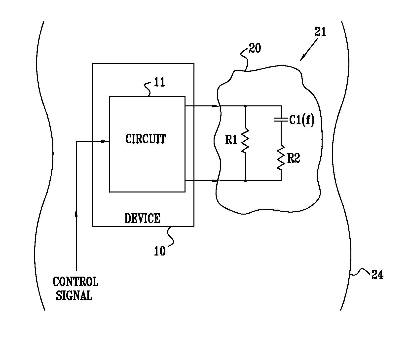
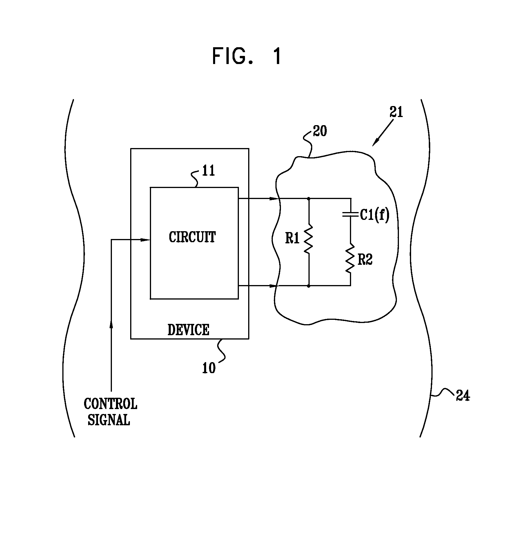
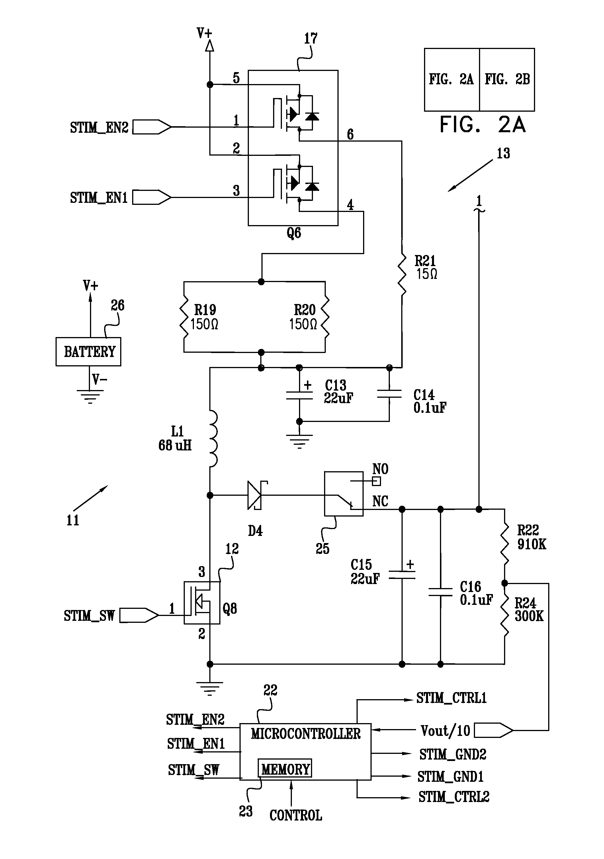
[0347]Reference is now made to FIG. 1, which is a schematic diagram illustrating a stimulation device 10, according to a preferred embodiment of the present invention. Device 10 comprises a circuit 11 which is used to generate electrical waveforms, the waveforms in turn stimulating tissue 20 of a subject 24. Preferably, tissue 20 comprises a muscle, most preferably a sphincter muscle, or a nerve of the subject, although it will be appreciated that tissue 20 may comprise any tissue of subject 24. Device 10 is preferably implanted in the subject, and after implantation and adjustment, is most preferably operated by a control signal generated by subject 24 and input to circuit 11. Circuit 11 may be implemented as discrete components, or as a custom-built component such as an application specific integrated circuit (ASIC), or as a combination of discrete and custom-built components. By way of example, the description hereinbelow applies when circuit 11 comprises discrete components.

[034...


PUM


Abstract

Apparatus is provided for applying current to a nerve of a subject, including a housing, adapted to be placed in a vicinity of the nerve; at least one cathode and at least one anode, fixed to the housing; a passive electrode, fixed to the housing; and a conducting element, which is electrically coupled to the passive electrode and is configured to extend to a remote location in a body of the subject at a distance of at least 1 cm from the housing. Other embodiments are also described.

Description

CROSS-REFERENCE TO RELATED APPLICATIONS[0001]The present application is a continuation-in-part of:[0002](a) U.S. patent application Ser. No. 13 / 804,825, filed Mar. 14, 2013, which published as US Patent Application Publication 2013 / 0211480, which is a continuation of U.S. patent application Ser. No. 10 / 538,521, filed Jan. 11, 2006, now U.S. Pat. No. 8,423,132, which is the US national stage of International Application PCT / IL03 / 01062, filed Dec. 11, 2003, which published as PCT Publication WO 04 / 052444 and claims priority from U.S. Provisional Application 60 / 432,932, filed Dec. 12, 2002;[0003](b) U.S. patent application Ser. No. 13 / 661,512, filed Oct. 26, 2012, which published as US Patent Application Publication 2013 / 0053936, which is a continuation of U.S. patent application Ser. No. 12 / 589,132, filed Oct. 19, 2009, now U.S. Pat. No. 8,326,438, which is a continuation of U.S. patent application Ser. No. 11 / 280,884, filed Nov. 15, 2005, now U.S. Pat. No. 7,627,384, which claims the...

Claims


Application Information

Patent Timeline
Patent Type & Authority Applications(United States)
IPC IPC(8): A61N1/05A61N1/375
CPCA61N1/0551A61N1/3756A61N1/05A61N1/14A61N1/36521A61N1/37A61N1/3716
Inventor AYAL, SHAICOHEN, EHUD
Owner MEDTRONIC INC
Learn More