Method and system for improved dilution tolerance

a technology of dilution tolerance and method, applied in the direction of electrical control, process and machine control, instruments, etc., can solve the problems of long transport delay, engine misfire events, and instability of combustion, so as to reduce throttling losses and combustion temperatures, improve fuel economy and vehicle emissions, and reduce the effect of combustion temperatur

Active Publication Date: 2015-02-26
FORD GLOBAL TECH LLC
View PDF5 Cites 25 Cited by
  • Summary
  • Abstract
  • Description
  • Claims
  • Application Information

AI Technical Summary

Benefits of technology

[0002]Exhaust gas recirculation (EGR) systems recirculate a portion of exhaust gas from an engine exhaust to an engine intake system to improve fuel economy and vehicle emissions by reducing throttling losses and combustion temperatures. In turbo-charged direct injection engines, a low-pressure EGR (LP-EGR) circuit may be implemented

Problems solved by technology

However the inventors herein have identified potential issues with such an approach.
Delivering EGR as per Ma may lead to combustion instability and engine misfire events during transient operations due to excess EGR dilution.
Particularly, in turbo-charged systems, providing EGR though the LP-EGR circuit may cause long transport delays, as the exhaust gases have to travel though the turbocharger compressor, high-pressure air induction plumbing, charge air cooler, and in

Method used


Image

  • Method and system for improved dilution tolerance
  • Method and system for improved dilution tolerance
  • Method and system for improved dilution tolerance

Examples


Embodiment Construction

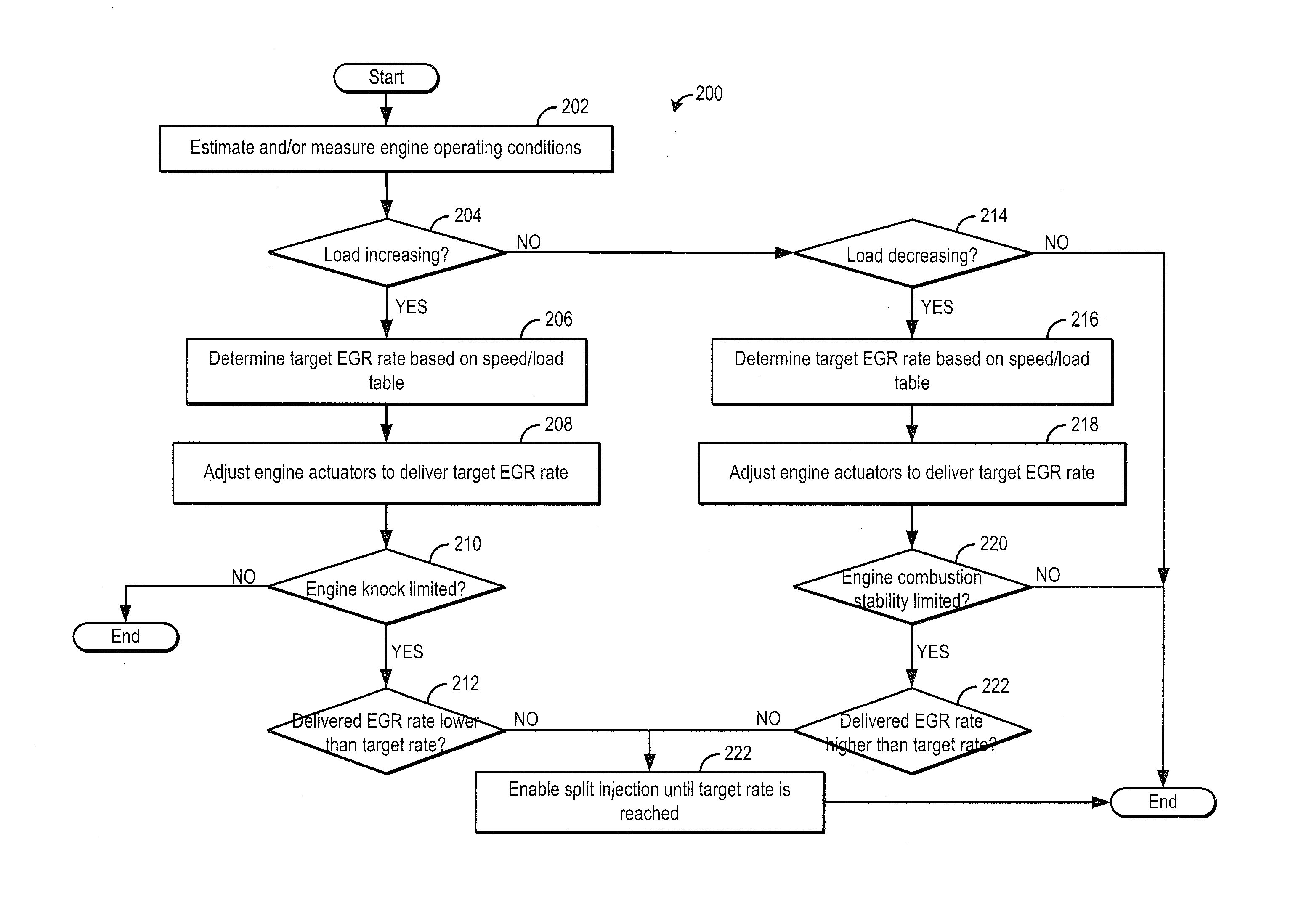
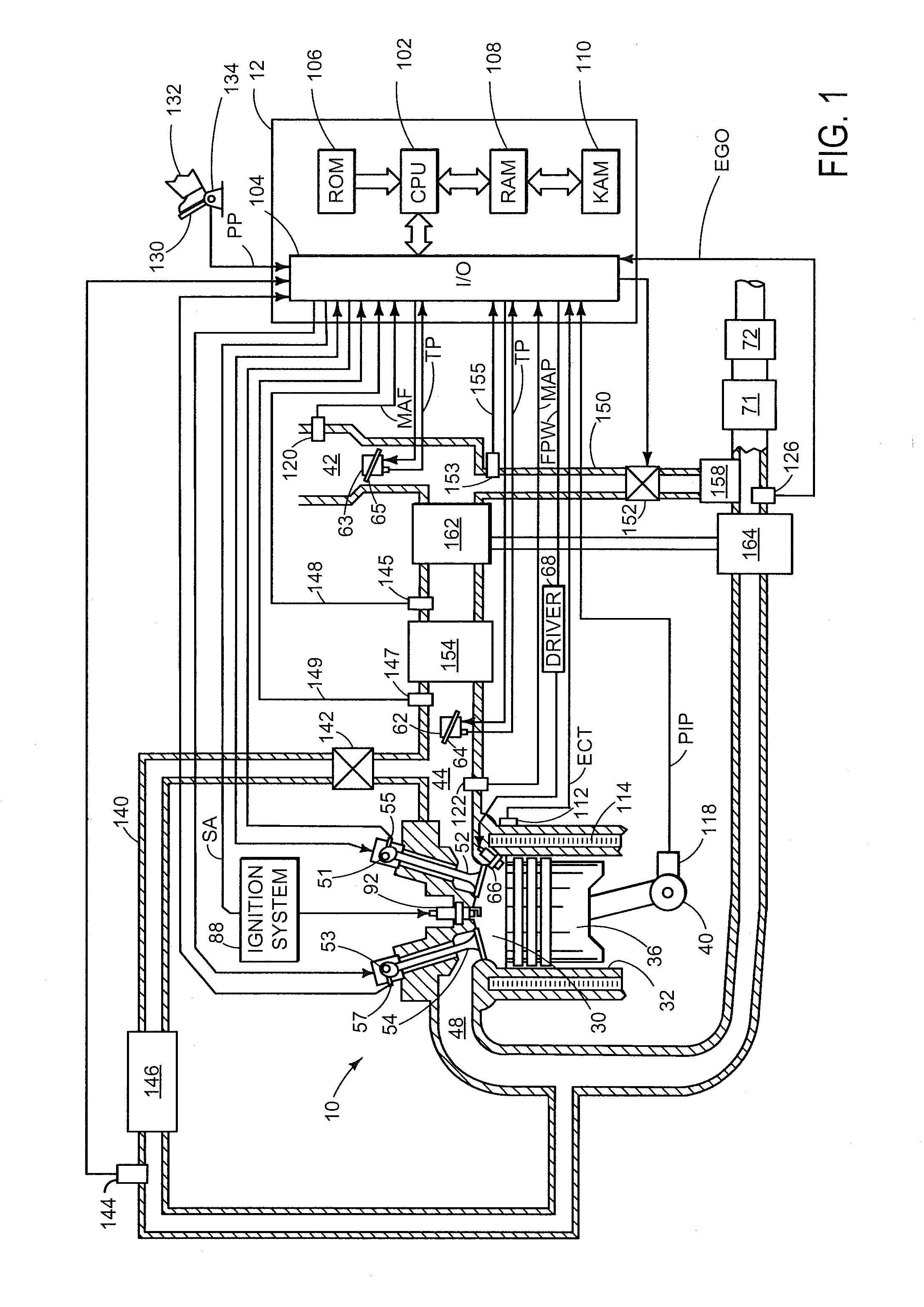
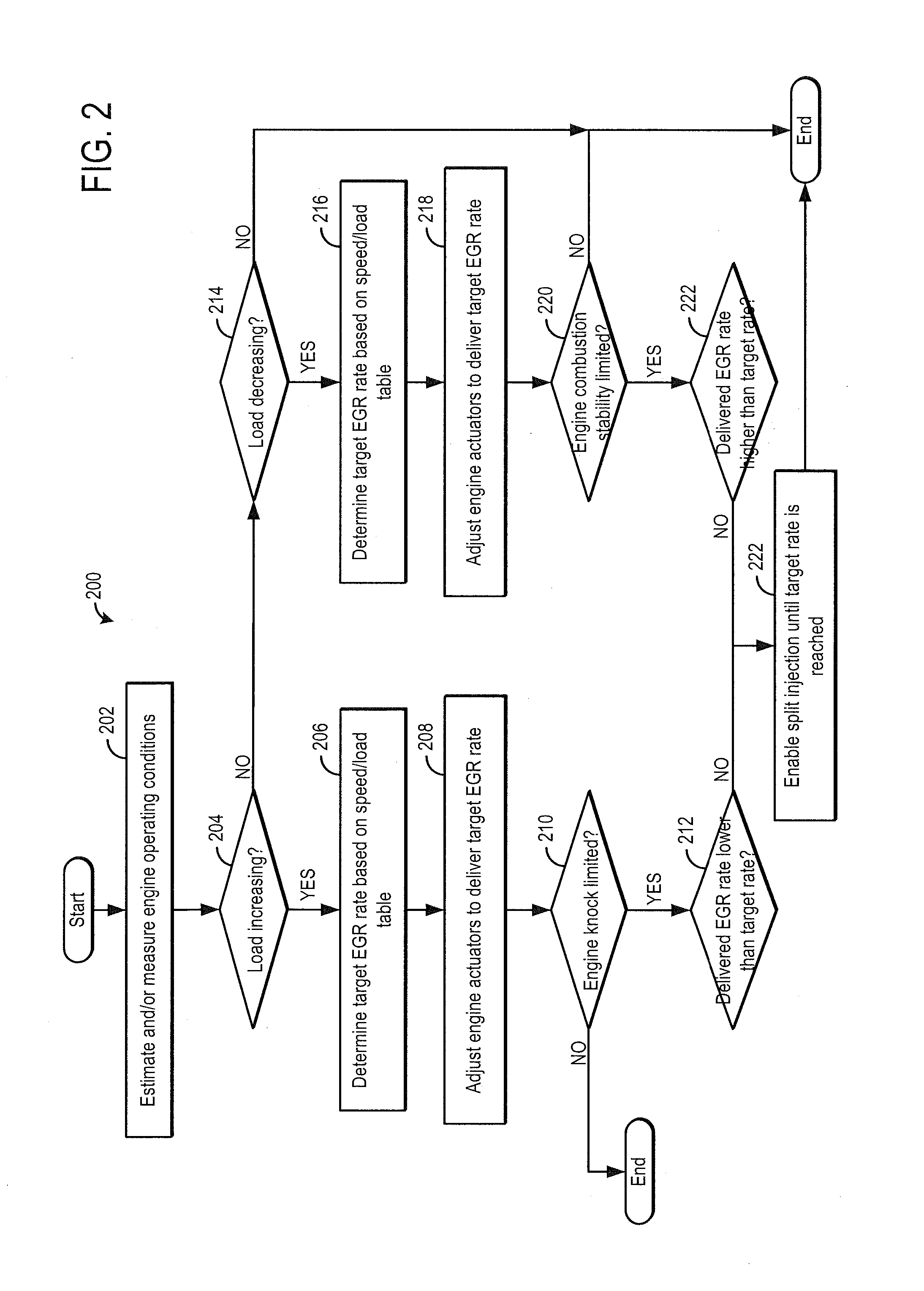
[0019]The present description relates to an EGR system coupled to a turbocharged engine in a motor vehicle. In one non-limiting example, the engine may be configured as part of the system illustrated in FIG. 1, wherein the engine includes at least one cylinder, a control system, a turbocharger, and an exhaust gas recirculation system, among other features. An engine controller may be configured to perform a control routine, such as the routine of FIGS. 2-4, to transiently shift to split fuel injection while ramping in LP-EGR to mitigate knock issues arising from delayed EGR delivery and transiently shift to split fuel injection while ramping out LP-EGR to improve engine dilution tolerance. The split fuel injection may include at least an intake stroke injection and a compression stroke injection, as depicted at FIGS. 5-7. Example engine adjustments during the ramping in or ramping out of the LP-EGR are shown at FIGS. 8 and 10. In this way, engine operation with EGR can be improved.

[...


PUM


Abstract

Methods and systems are provided for improving combustion stability, in particular during transient operations such as tip-out to lower load conditions, when EGR is being purged. Until a desired LP-EGR rate is achieved, fuel may be delivered as a split injection with at least an intake stroke injection and a compression stroke injection. Subsequently, single fuel injection may be resumed.

Description

TECHNICAL FIELD[0001]The present application relates to methods and systems for improving exhaust gas recirculation dilution tolerance of an engine during operation at light loads.BACKGROUND AND SUMMARY[0002]Exhaust gas recirculation (EGR) systems recirculate a portion of exhaust gas from an engine exhaust to an engine intake system to improve fuel economy and vehicle emissions by reducing throttling losses and combustion temperatures. In turbo-charged direct injection engines, a low-pressure EGR (LP-EGR) circuit may be implemented. The LP-EGR circuit recirculates exhaust gases from an exhaust passage downstream of a turbine to an intake passage upstream of a turbocharger compressor. In order to provide EGR over a wide-range of operating conditions, LP-EGR systems may utilize a flat EGR schedule wherein a fixed EGR percentage of fresh airflow may be maintained.[0003]One example approach for providing desired EGR dilution is shown by Ma et. al in U.S. Pat. No. 6,014,959. Therein, a r...

Claims


Application Information

Patent Timeline
IPC IPC(8): F02D43/00
CPCF02D43/00F02D41/045F02D41/107F02D41/1498F02D41/402F02D35/027F02D41/0005F02D2200/602F02D41/005F02M26/06Y02T10/40F02D41/0007F02D41/0052F02D41/0077F02D43/04
Inventor WOOLDRIDGE, STEVENSURNILLA, GOPICHANDRAYI, JIANWEN JAMESBOYER, BRAD ALANHILDITCH, JAMES ALFREDSHELBY, MICHAEL HOWARDPETERSEN, BENJAMIN RICHARD
Owner FORD GLOBAL TECH LLC
Why Eureka
Try Eureka