
Active Temperature Control for Induction Heating

a technology of active temperature control and induction heating, which is applied in the field of active temperature control of induction heating system, can solve the problems of irreversible damage, additional heat produced within magnetic parts through hysteresis, and so as to reduce increase the heat generated by magnetic materials, and reduce the effect of hysteresis

Active Publication Date: 2015-03-05
AIRBUS SAS +1
View PDF1 Cites 16 Cited by
  • Summary
  • Abstract
  • Description
  • Claims
  • Application Information

AI Technical Summary

Benefits of technology

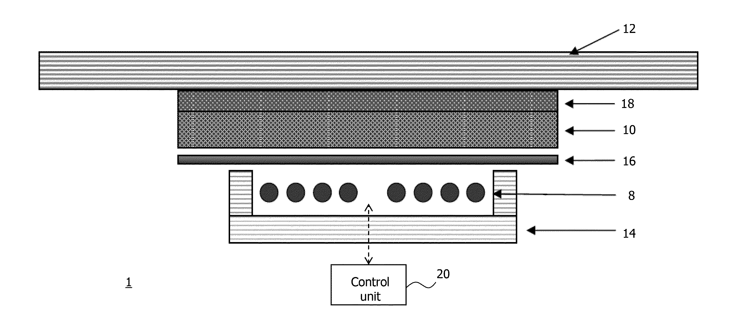
The patent describes a method for controlling the temperature of a magnetic load to prevent damage to a workpiece. When the magnetic material reaches its Curie temperature, the generation of heat based on the hysteresis effect is reduced, resulting in a decrease in the amount of energy produced or generated by the magnetic load. This reduces the amount of energy transferred to and absorbed by the workpiece. A metallic shield layer can be used to shield the workpiece from the alternating magnetic field and support heat distribution. The alternating magnetic field can be adjusted to control the temperature of the magnetic material. The control cycle may depend on the properties of the magnetic material, such as its thermal conductivity.

Problems solved by technology

This (rapid) flipping of the magnetic domains causes considerable friction and thus produces heat inside the material.
In consequence, additional heat is produced within magnetic parts through hysteresis.
Moreover, the local temperatures should not exceed a critical temperature which would lead to irreversible damage or should not undershoot temperatures which are not sufficient for a reliable curing process.
However, these methods do not generally guarantee uniform volume heating.
Induction heating systems based on ferri- and ferromagnetic magnetic materials are, in principle, available but their application to the curing process of composites is limited due to loss mechanisms in magnetic materials and therefore due to the difficulty to control the temperature field.

Method used


Image

  • Active Temperature Control for Induction Heating
  • Active Temperature Control for Induction Heating
  • Active Temperature Control for Induction Heating

Examples


Embodiment Construction

[0050]Hereinbelow, without being limited thereto, specific details are set out in order to provide a complete understanding of the present invention. It is, however, clear to a person skilled in the art that the present invention may be used in other embodiments which may deviate from the details set out below. Even if, by way of example, the embodiments hereinbelow are described with reference to certain materials to illustrate certain effects caused by these materials, the embodiments set out below are not limited thereto, but can be used without limitation with other materials providing the same or similar effects. Further, even if hereinbelow it is referred to an induction coil for generating a magnetic field, it is conceivable that other inductors may be used instead.

[0051]It is clear to a person skilled in the art that the explanations set out below are / may be implemented using hardware circuits, software means or a combination thereof. The software means may be associated wit...


PUM


Abstract

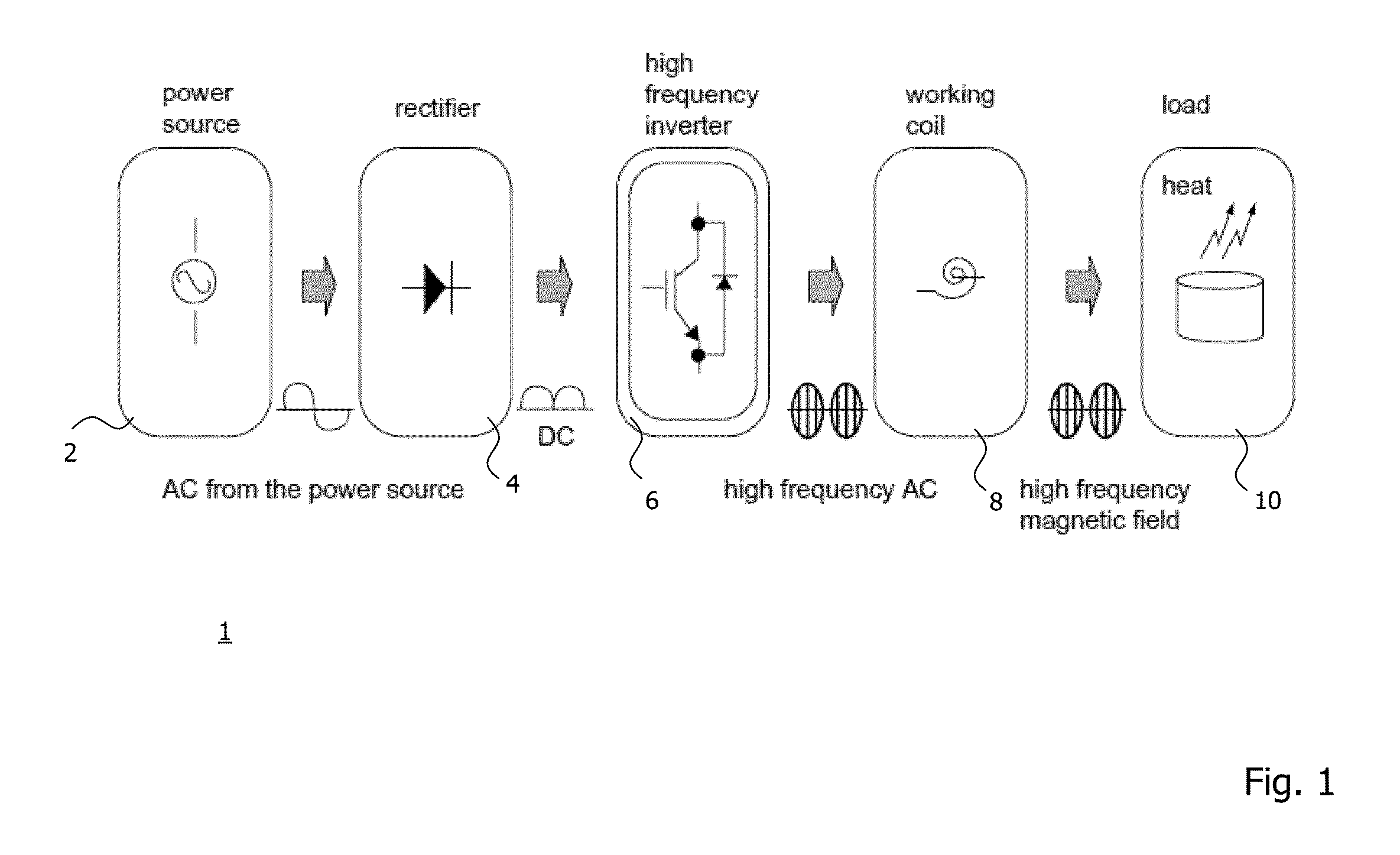
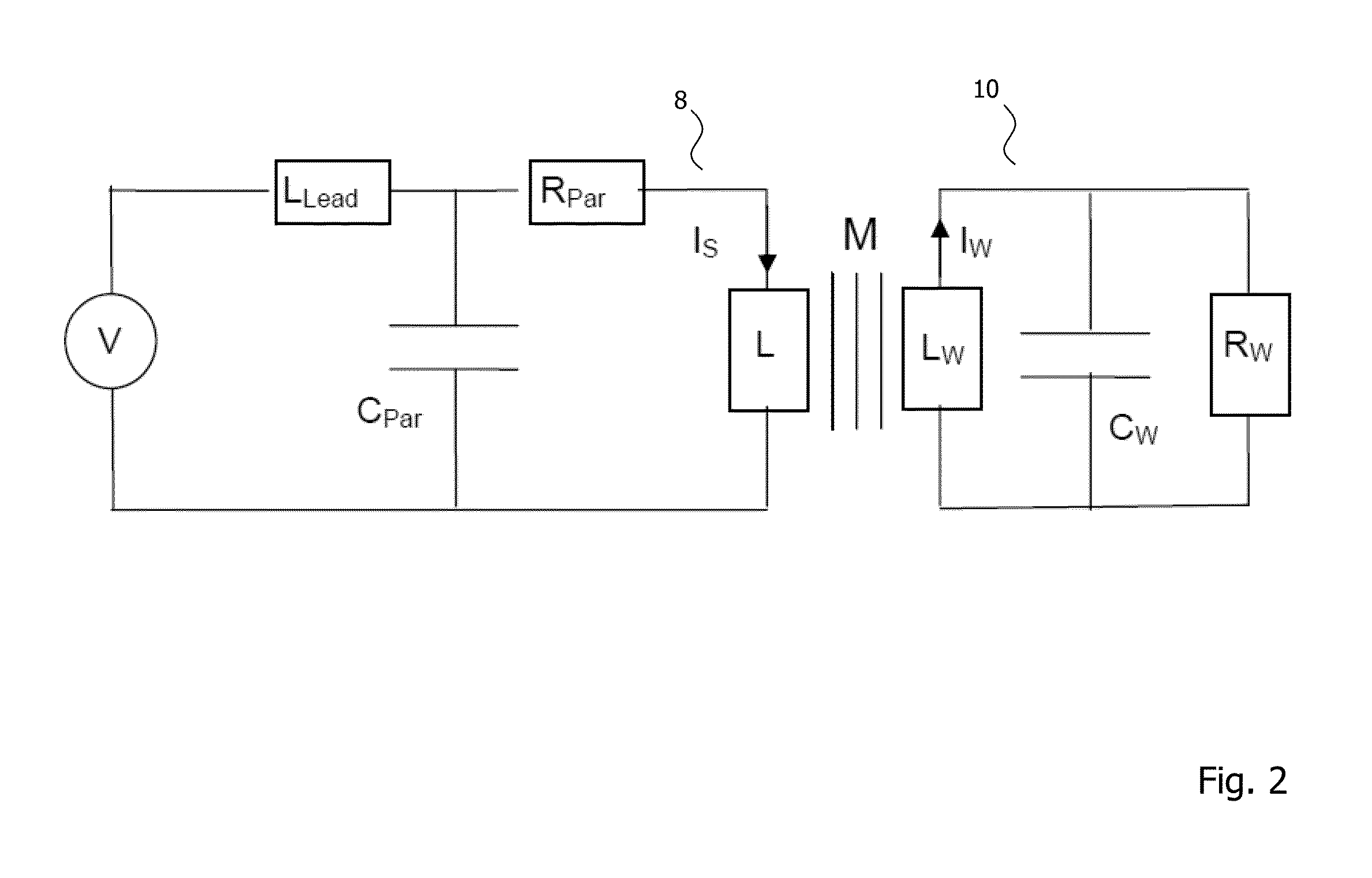
An induction heating system and a method for controlling a process temperature for induction heating of a workpiece. The induction heating system comprises an inductor configured to generate an alternating magnetic field in response to an alternating current supplied thereto, a magnetic load comprising a magnetic material, the magnetic material having a Curie temperature and being configured to generate heat in response to the alternating magnetic field being applied thereto, the magnetic load being connectable to the workpiece in a heat-conducting manner so as to transfer the generated heat to the workpiece, and a control unit configured to control the process temperature for manufacturing the workpiece by adjusting the alternating magnetic field when the temperature of the magnetic material is in a temperature control range around or below the Curie temperature of the magnetic material, the temperature control range being dependent on the magnetic material of the magnetic load.

Description

CROSS-REFERENCES TO RELATED APPLICATIONS[0001]This application claims the benefit of the European patent application No. 13182142.3 filed on Aug. 29, 2013, the entire disclosures of which are incorporated herein by way of reference.BACKGROUND OF THE INVENTION[0002]The present invention generally relates to induction heating. More particularly, the present invention relates to an induction heating system and a method for controlling a process temperature for induction heating of a workpiece.[0003]Induction heating may be used in multiple different manufacturing processes or steps, e.g., to bond, to cure, to harden or soften metals or other conductive or non-conductive materials.[0004]In a basic induction heating setup, a power supply provides and sends an alternating current to and through an inductor. The inductor is often formed as a coil, for example, a copper coil. In induction heating, typically, a source of high frequency electricity is used to drive an alternating current thro...

Claims


Application Information

Patent Timeline
Patent Type & Authority Applications(United States)
IPC IPC(8): H05B6/06H05B6/10
CPCH05B6/105H05B6/06H05B2206/023
Inventor KARCH, CHRISTIANSTEINWANDEL, JUERGENFIETZEK, HEIKOFIDEU, PAULINDUPRIEU, BERNARD
Owner AIRBUS SAS
Learn More