
Photoelectric encoder

a technology of encoder and encoder, applied in the field of photoelectric encoder, can solve the problems of large device size high cost, etc., and achieve the effects of high cost, reduced device size, and high cos

Active Publication Date: 2015-03-05
MITUTOYO CORP
View PDF1 Cites 9 Cited by
  • Summary
  • Abstract
  • Description
  • Claims
  • Application Information

AI Technical Summary

Benefits of technology

The present invention aims to provide a photoelectric encoder that can have a large gap between a scale and a detection head without using a lens, and can detect pseudo-random data on the scale. The technical effect of this invention is that it reduces device size and costs while achieving the same level of accuracy.

Problems solved by technology

There is thus a problem that the device size is large and the costs are high.
Although this reduces the device size, there is still the problem of high costs.
However, when the distance between the scale and the photo detector is large, a light ray having passed through the pseudo-random pattern diverges, and the photo detector cannot detect the pseudo-random pattern as the pseudo-random pattern.
However, even if the parallel light is emitted, when the distance between the scale and the photo detector is large, light diffraction occurs due to the interaction between the pseudo-random pattern and the parallel light.
Therefore, a gap between the scale and the detection head cannot be enlarged.
However, if the gap between the scale and the detection head is too narrow, there is a problem that measurement of the encoder cannot be carried out when the gap varies due to scale flexure or when a foreign matter such as metal powder enters.

Method used


Image

  • Photoelectric encoder
  • Photoelectric encoder
  • Photoelectric encoder

Examples


first embodiment

[0040]Exemplary embodiments of the present invention are described hereinafter with reference to the drawings.

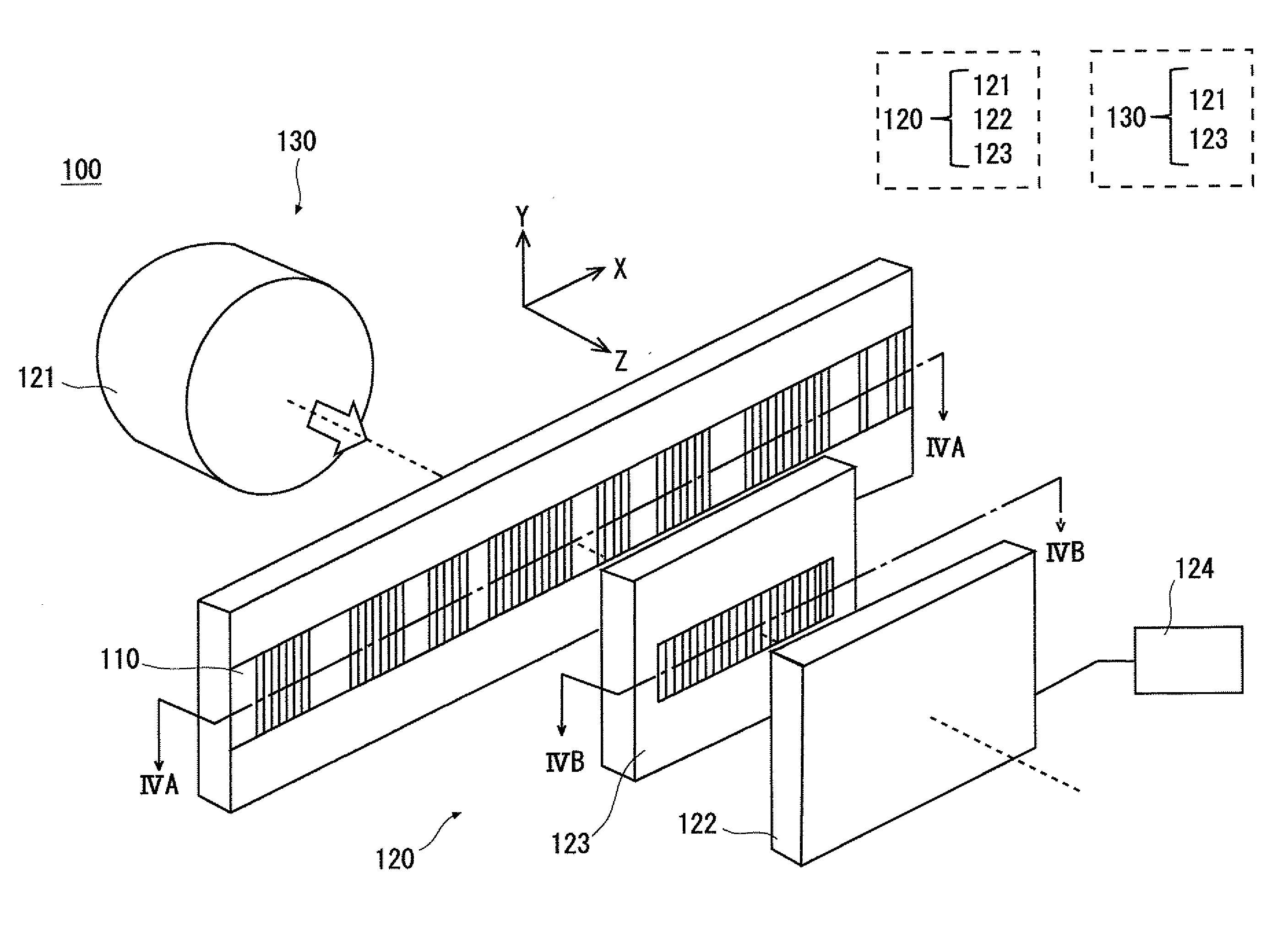
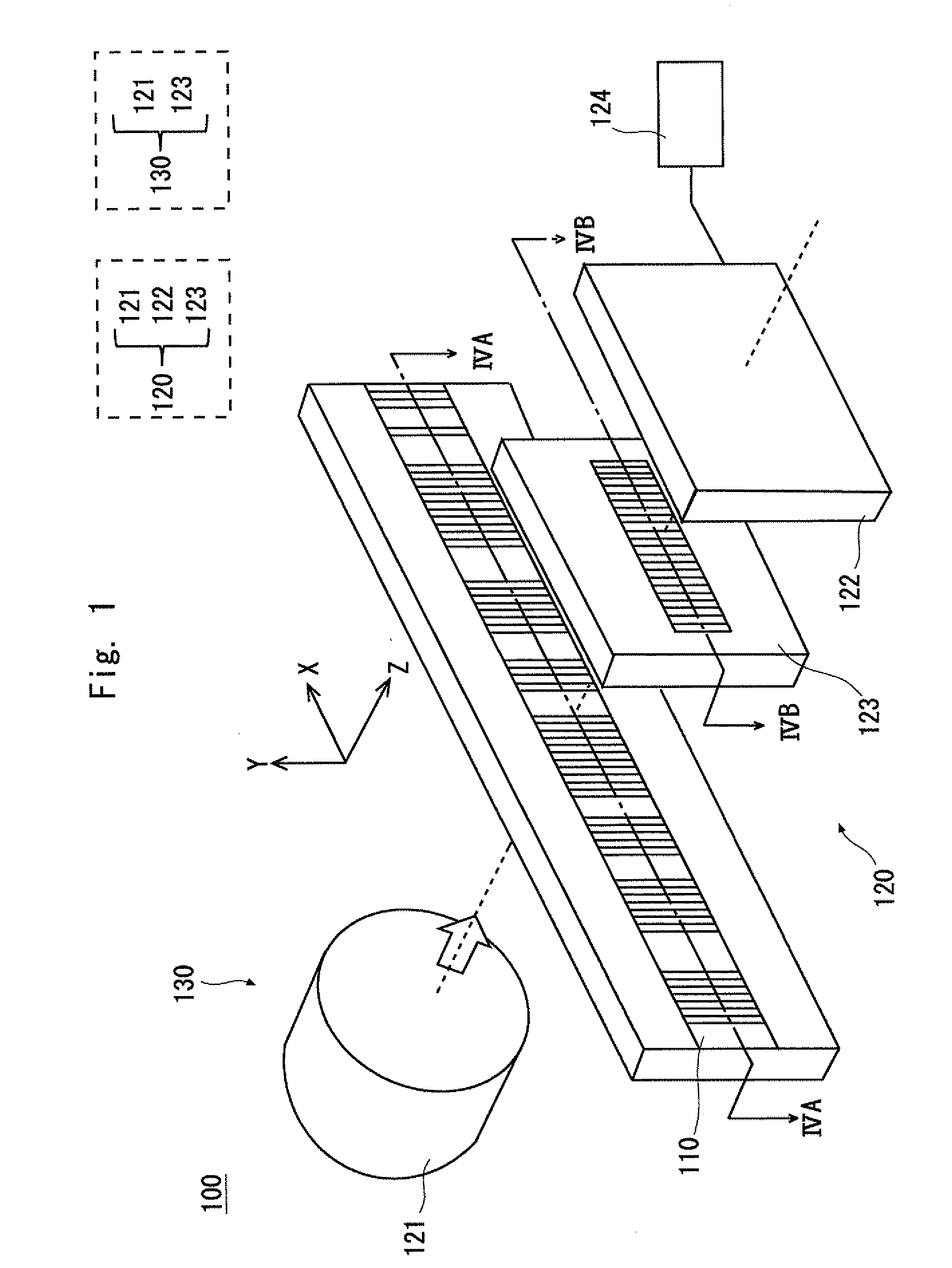
[0041]FIG. 1 is a view showing a structure of a photoelectric encoder 100 according to a first embodiment. The photoelectric encoder 100 includes an absolute scale 110 and a detection head 120. The detection head 120 can move along the absolute scale 110 in the measurement axis direction, and the absolute position of the detection head 120 with respect to the absolute scale 110 is detected. The detection head 120 includes an incoherent light source 121, a light receiving unit 122, and an interference pattern signal processing unit 124. Further, in the detection head 120 of the photoelectric encoder 100 according to the first embodiment, an absolute auxiliary grating 123 is placed between the absolute scale 110 and the light receiving unit 122.

[0042]The incoherent light source 121 shown in FIG. 1 emits incoherent light. As the incoherent light source 121, LED (Light Emitting ...

second embodiment

[0079]FIG. 13 is a view showing a structure of a photoelectric encoder 700 according to a second embodiment of the present invention. The photoelectric encoder 700 includes an absolute (ABS) scale 110, an incremental (INC) scale 714, and a detection head 720. The photoelectric encoder 700 detects the absolute position of the detection head 720 with respect to the ABS scale 110 and further detects the relative moving amount of the detection head 720 with respect to the INC scale 714. The detection head 720 includes an incoherent light source 121, a light receiving unit 122, and an interference pattern signal processing unit 124. Further, the photoelectric encoder 700 according to this embodiment includes an absolute (ABS) auxiliary grating 123 and an incremental (INC) auxiliary grating 726 between the absolute scale 110 and the INC scale 714, and the light receiving unit 122.

[0080]FIG. 14 is a view showing a structure of a scale according to the second embodiment. As shown in FIG. 14...

third embodiment

[0108]FIG. 16 is a view showing a structure of a photoelectric encoder according to a third embodiment of the present invention. As shown in FIG. 16, the photoelectric encoder 1000 according to the third embodiment of the invention includes an absolute (ABS) scale 110, an incremental (INC) scale 714, and a detection head 1020. The detection head 1020 includes a coherent light source 1021, a light receiving unit 122, and an interference pattern signal processing unit 124.

[0109]The photoelectric encoder 1000 according to this embodiment detects the absolute position of the detection head 1020 with respect to the ABS scale 110 and further detects the relative moving amount of the detection head 1020 with respect to the INC scale 714.

[0110]The coherent light source 1021 emits coherent light. As the coherent light source 1021, a semiconductor laser is used, for example.

[0111]FIG. 17 is a cross-sectional view on the ABS scale side of the photoelectric encoder 1000 according to this embodi...


PUM


Abstract

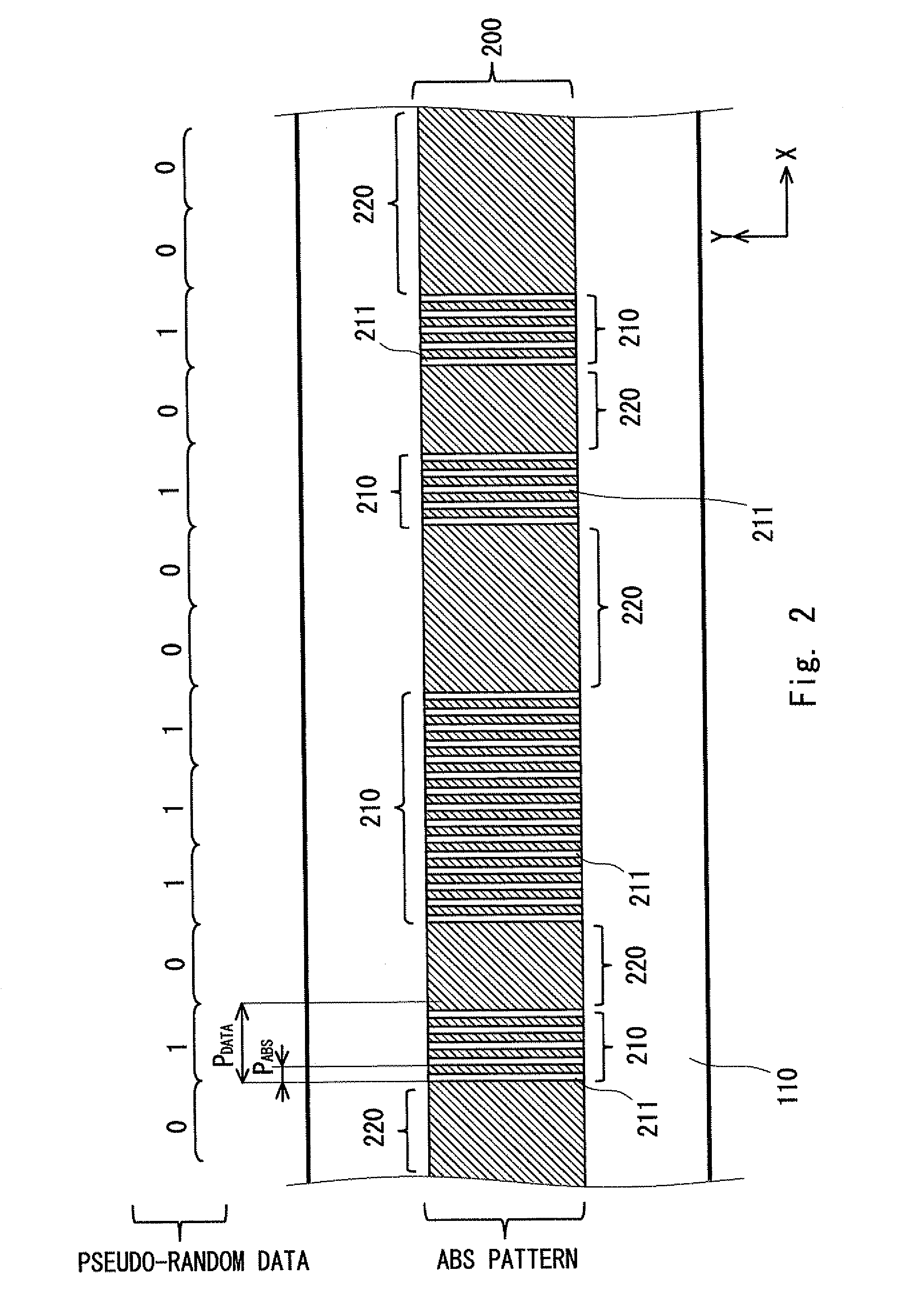
A photoelectric encoder includes an absolute scale provided with an absolute pattern based on pseudo-random data, and a detection head including a light source that emits light to the absolute pattern of the absolute scale, and a light receiving unit that receives light from the absolute pattern, and it detects an absolute position of the detection head with respect to the absolute scale. In the photoelectric encoder, the absolute pattern is composed of a grating part and a dark part arranged in a repetitive manner. The photoelectric encoder further includes an interference pattern generation means that generates an interference pattern in combination with the grating part, and an interference pattern signal processing unit that detects the pseudo-random data of the absolute pattern based on the interference pattern received by the light receiving unit.

Description

INCORPORATION BY REFERENCE[0001]This application is based upon and claims the benefit of priority from Japanese patent application No. 2013-181784, filed on Sep. 3, 2013, the disclosure of which is incorporated herein in its entirety by reference.BACKGROUND OF THE INVENTION[0002]1. Field of the Invention[0003]The present invention relates a photoelectric encoder.[0004]2. Description of Related Art[0005]A photoelectric absolute encoder that obtains an absolute position by detecting a pseudo-random pattern placed on a scale is known. As the pseudo-random pattern on the scale, a pattern called M-sequence code can be used for example (“Absolute position measurement using optical detection of coded patterns”, J T M Stevenson et. al, J. Phys, E:Sci. Instrum. 21(1988) 1140-1145). The absolute encoder disclosed in Japanese Unexamined Patent Application Publication No. H07-286861 guides an image of a pseudo-random pattern on a scale to a detector using a lens and thereby detects the position...

Claims


Application Information

Patent Timeline
Patent Type & Authority Applications(United States)
IPC IPC(8): G01D5/347
CPCG01D5/34784G01D5/34746G01D5/34715G01D5/34723
Inventor YAKU, TORUKATO, YOSHIAKI
Owner MITUTOYO CORP
Learn More