
Electric compressor

a technology of electric compressor and compressor, applied in the direction of positive displacement liquid engine, piston pump, machine/engine, etc., can solve problems such as heat generation, and achieve the effect of improving the reliability of electric compressor

Inactive Publication Date: 2015-03-05
TOYOTA IND CORP
View PDF4 Cites 20 Cited by
  • Summary
  • Abstract
  • Description
  • Claims
  • Application Information

AI Technical Summary

Benefits of technology

The present invention relates to an electric compressor that can effectively cool a damping resistor of a filter circuit to improve its reliability. The technical effect of this invention is to lower the resonance level of the filter circuit and increase the efficiency of the electric compressor.

Problems solved by technology

However, the use of the LC filter results in resonance by L (reactance) of a coil and C (capacitance) of a capacitor at a specific frequency.
This may result in heat generation.

Method used


Image

  • Electric compressor
  • Electric compressor
  • Electric compressor

Examples


Embodiment Construction

[0024]The following describes an embodiment of the present invention in detail with reference to figures. It should be noted that the same or corresponding portions in figures are given the same reference characters and are not described repeatedly.

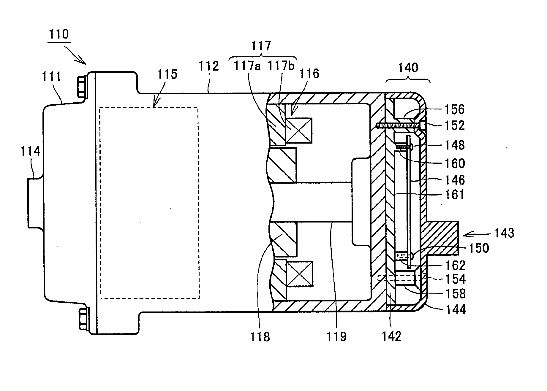
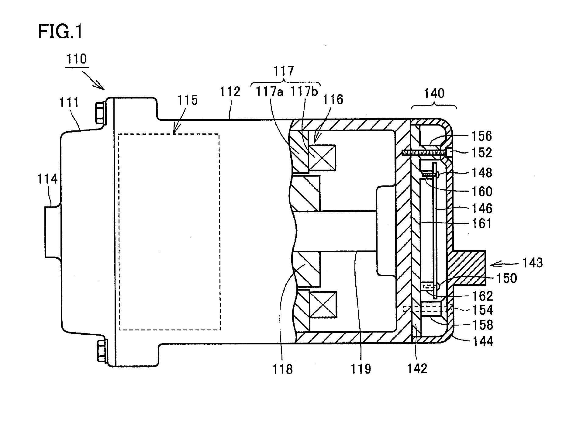
[0025]FIG. 1 shows an entire configuration of an electric compressor of the present embodiment. Referring to FIG. 1, the electric compressor 110 includes: a housing formed by joining an discharge housing 111, which has a cover-like shape and is made of aluminum (metal material), to a suction housing 112, which has a shape of cylinder with a bottom and is made of aluminum (metal material); a compressing unit 115 and an electric motor 116, which are accommodated in the suction housing 112; and an inverter unit 140 attached to the suction housing 112 such that the inverter unit 140 is incorporated with the suction housing 112.

[0026]A suction port not shown in the figure is formed at the bottom portion side of the circumferential wall of the ...


PUM


Abstract

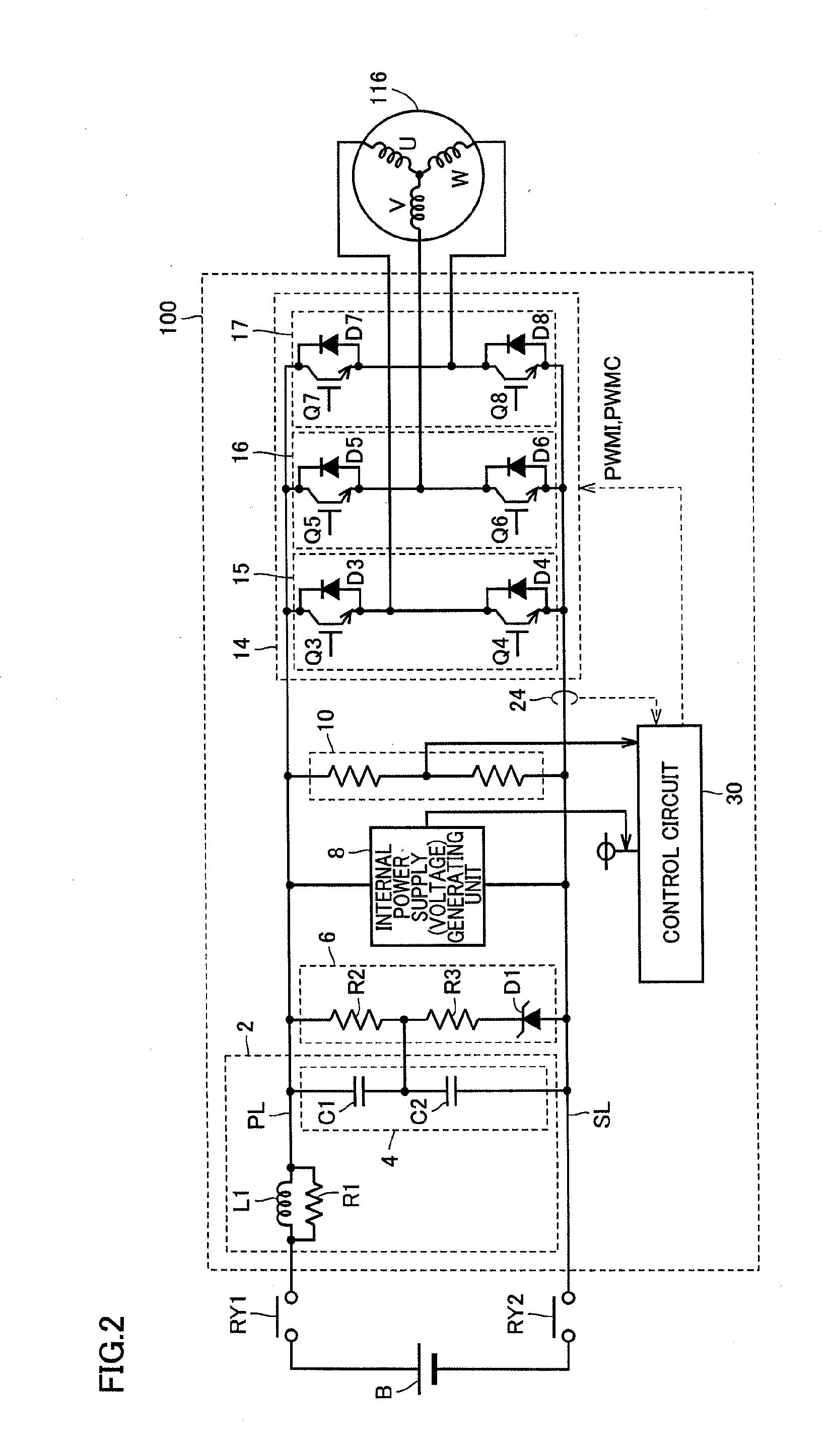
An electric compressor includes: a compressing unit; an electric motor that rotates the compressing unit; and a driving circuit. The driving circuit includes a filter circuit, an inverter circuit that receives electric power from the power supply line via the filter circuit, and a circuit board on which the inverter circuit is disposed, and a base member (aluminum base) and that supports the circuit board. The filter circuit has an electromagnetic coil and a damping resistor. The damping resistor is fixed to the aluminum base in abutment with the aluminum base. Preferably, the filter circuit is mounted on the circuit board, and the damping resistor has a lead line soldered to the circuit board and is fixed to the aluminum base by a screw. With this, there can be provided the electric compressor capable of effectively cooling the damping resistor of the filter circuit.

Description

[0001]This nonprovisional application is based on Japanese Patent Application No. 2013-182045 filed on Sep. 3, 2013, with the Japan Patent Office, the entire contents of which are hereby incorporated by reference.BACKGROUND OF THE INVENTION[0002]1. Field of the Invention[0003]The present invention relates to an electric compressor, in particular, an electric compressor provided with a filter circuit in a power supply input portion.[0004]2. Description of the Background Art[0005]As electric compressors for vehicles, there has been developed an electric compressor in which a driving circuit for driving a motor is incorporated for size reduction. If switching noise of the driving circuit of the electric compressor is leaked to outside, an adverse effect may be provided on a radio of the vehicle or the like. To address such a case, a filter circuit is generally provided in a power supply input portion thereof.[0006]Japanese Patent Laying-Open No. 2010-48103 has discussed to dispose a lo...

Claims


Application Information

Patent Timeline
IPC IPC(8): H02K9/00H02K11/00
CPCH02K11/0068H02K9/00F04B35/04H02K11/33H02K11/02H02K11/05H02K11/026H02K11/028F04B39/06F04B49/10H02K11/049
Inventor YANO, JUNYAMIZUNO, TAKUROSUITOU, KENTAKAHATA, JUNICHIKAGAWA, FUMIHIROENAMI, SHINGO
Owner TOYOTA IND CORP
Learn More