
Hybrid Ionomer Electrochemical Devices

a technology of hybrid ionomer and electrochemical device, which is applied in the direction of electrochemical generator, fuel cell, cell components, etc., can solve the problems of carbon monoxide poisoning, sluggish reaction kinetics of pemfc's, etc., and achieve the effect of reducing species

Inactive Publication Date: 2015-03-05
GEORGIA TECH RES CORP
View PDF2 Cites 5 Cited by
  • Summary
  • Abstract
  • Description
  • Claims
  • Application Information

AI Technical Summary

Benefits of technology

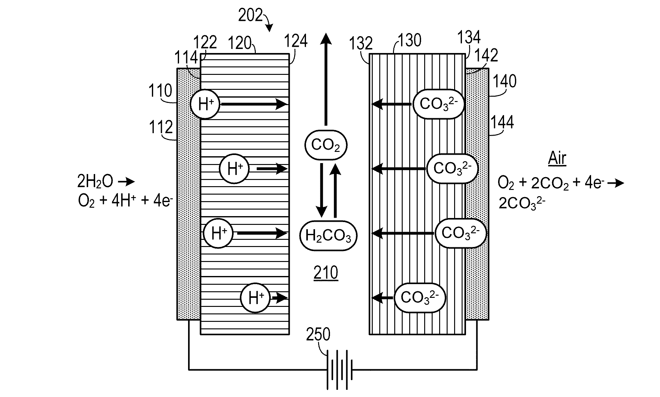
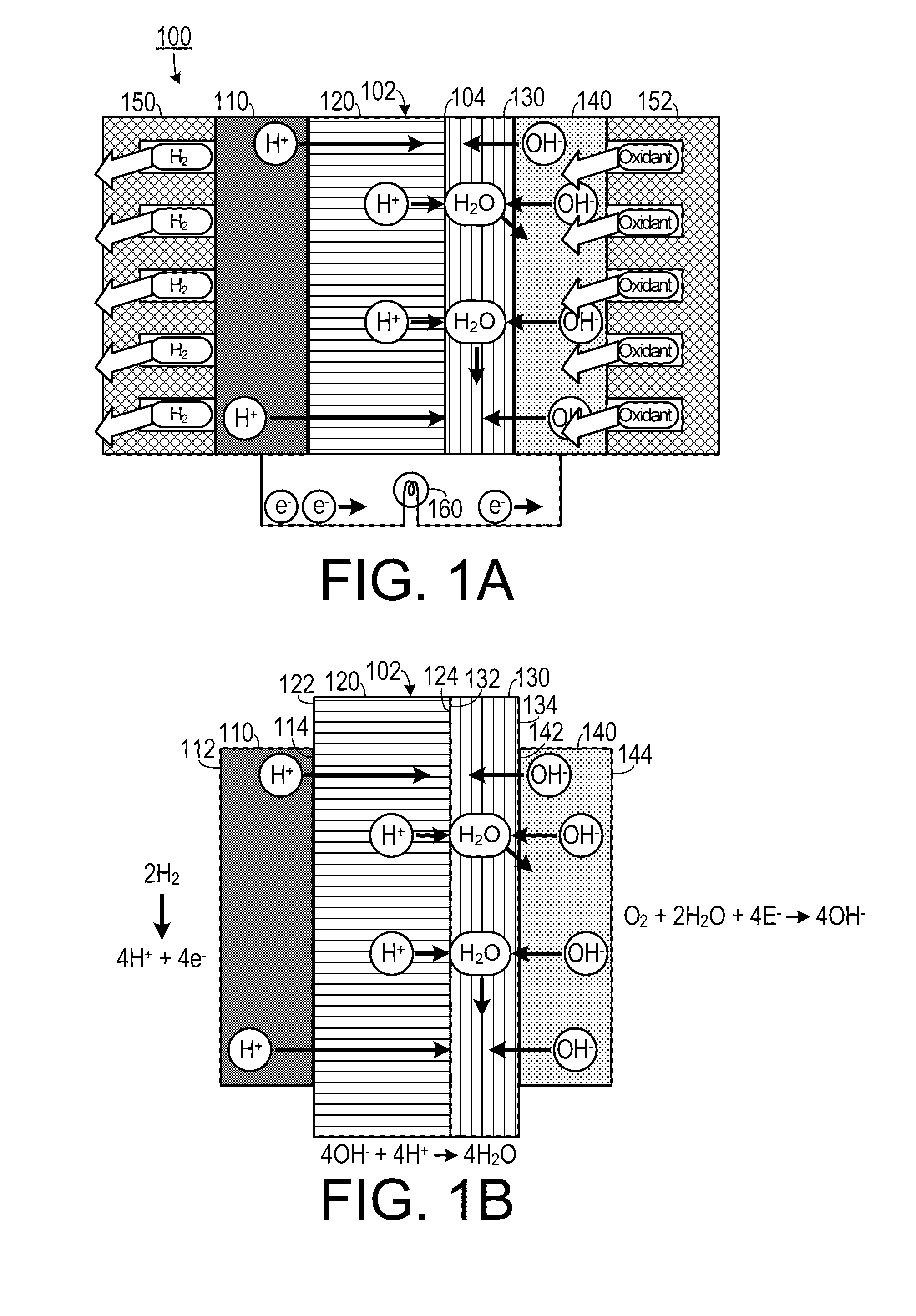
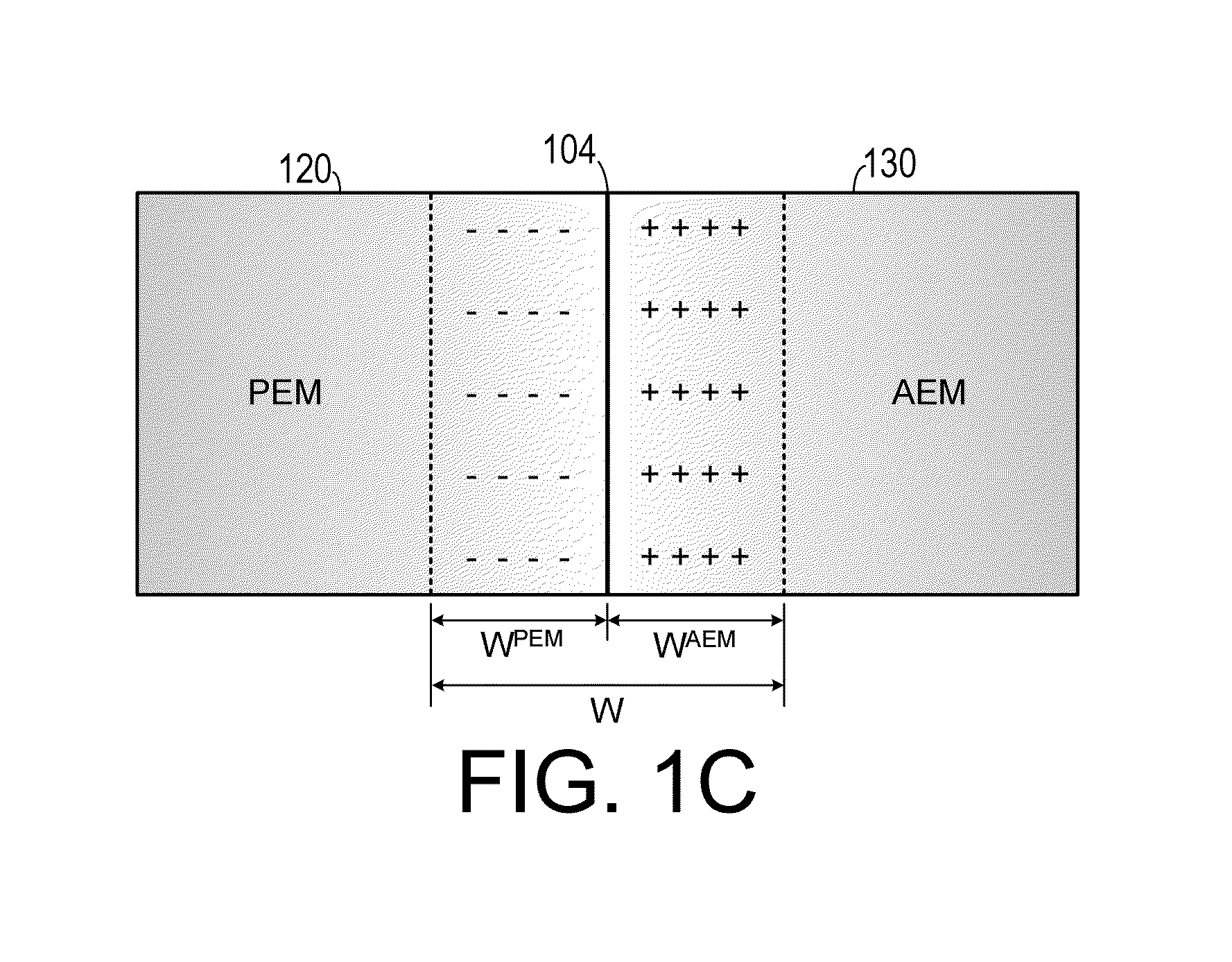
The present invention is a membrane electrode assembly for a fuel cell that can convert a reducing agent to electrical energy. It includes an anode electrode with a first catalyst that separates the reducing agent into positively charged ions and negative charges, a proton exchange membrane that favors the transport of positively charged ions, an anion exchange membrane that favors the transport of negatively charged ions, and a cathode electrode with a second catalyst that reacts with an oxidizing agent to create reduced species. The membrane electrodes are designed to allow the efficient and reliable conversion of reducing agents to electrical energy. The invention also includes an electrochemical device that utilizes the membrane electrodes to generate electrical energy from a reducing agent.

Problems solved by technology

Although PEMFC's have been successfully used in numerous applications, several disadvantageous features impede wide-scale commercialization of PEMFC's.
For example, PEMFC's exhibit sluggish reaction kinetics, complex water management, carbon monoxide poisoning, limited lifetime due to membrane and electrode degradation and they require expensive noble metal catalysts and perfluorinated membranes.
Such carbonate poising presents a major obstacle in conventional alkaline fuel cells, which use sodium or potassium hydroxide as an electrolyte.
This is a concern because it may lower the performance of the fuel cell.

Method used


Image

  • Hybrid Ionomer Electrochemical Devices
  • Hybrid Ionomer Electrochemical Devices
  • Hybrid Ionomer Electrochemical Devices

Examples


Embodiment Construction

[0024]A preferred embodiment of the invention is now described in detail. Referring to the drawings, like numbers indicate like parts throughout the views. Unless otherwise specifically indicated in the disclosure that follows, the drawings are not necessarily drawn to scale. As used in the description herein and throughout the claims, the following terms take the meanings explicitly associated herein, unless the context clearly dictates otherwise: the meaning of “a,”“an,” and “the” includes plural reference, the meaning of “in” includes “in” and “on.” Also as used herein, “negative charges,”“negatively charged ions” and “negatively charged particles” include electrons; “positive charges,”“positively charged ions” and “positively charged particles” include protons.

[0025]As shown in FIGS. 1A and 1B, one embodiment of an electrochemical device that may be configured to generate electricity, such as a fuel cell 100, includes a hybrid membrane electrode assembly 102 surrounded by a fuel...


PUM


Abstract

A membrane electrode assembly for use in a fuel cell includes an anode electrode, a proton exchange membrane, an anion exchange membrane and a cathode electrode. The anode electrode includes a first catalyst. The first catalyst separates a reducing agent into a plurality of positively charged ions and negative charges. The proton exchange membrane is configured to favor transport of positively charged ions therethrough and is also configured to inhibit transport of negatively charged particles therethrough. The anion exchange membrane is configured to favor transport of negatively charged ions therethrough and is also configured to inhibit transport of positively charged ions therethrough. The cathode electrode includes a second catalyst and is disposed adjacent to a second side of the anion exchange membrane. The second catalyst reacts electrons with the at least one oxidizing agent so as to generate+reduced species.

Description

CROSS-REFERENCE TO RELATED APPLICATION(S)[0001]This application claims the benefit of U.S. Provisional Patent Application Ser. No. 61 / 085,631, filed Aug. 1, 2008, the entirety of which is hereby incorporated herein by reference.[0002]This application is a continuation-in-part of, and claims the benefit of, U.S. patent application Ser. No. 12 / 534,117, filed Aug. 1, 2009, the entirety of which is hereby incorporated herein by reference.STATEMENT OF GOVERNMENT INTEREST[0003]This invention was made with government support under agreement No. CTS-0624620, awarded by the National Science Foundation. The government has certain rights in the invention.BACKGROUND OF THE INVENTION[0004]1. Field of the Invention[0005]The present invention relates to electrochemical devices and, more specifically, to electrochemical devices that employ ion exchange membranes.[0006]2. Description of the Related Art[0007]Fuel cells have the potential to provide clean and efficient energy sources for stationary, t...

Claims


Application Information

Patent Timeline
IPC IPC(8): H01M8/04H01M4/90H01M4/92H01M8/10
CPCH01M8/04141H01M8/1039H01M8/103H01M2300/0082H01M4/9041H01M4/921H01M2008/1095H01M8/1032H01M8/1004H01M8/1023H01M8/1027H01M8/1053Y02E60/50
Inventor UNLU, MURATKOHL, PAULZHOU, JUNFENG
Owner GEORGIA TECH RES CORP
Learn More