Simplified arthroscopy cannula

a cannula and simplified technology, applied in the field of endoscopic surgery cannula, can solve the problems of weakening the bond to the point of failure, difficult to confirm the integrity of the bond, and costly time-consuming procedures for validation of the bonding process, so as to reduce manufacturing costs, increase reliability, and strengthen the reliability of the bonding element.

Inactive Publication Date: 2015-03-05
HANSHI
View PDF3 Cites 30 Cited by
  • Summary
  • Abstract
  • Description
  • Claims
  • Application Information

AI Technical Summary

Benefits of technology

[0009]In the course of researching the afore-mentioned problems in the arthroscopic arts, the present inventors discovered one could eliminate the need for a bond between the distal and proximal elements of a cannula through the use of a suitable mechanical joining means provided in the configuration of the elements. Specifically, one could configure the elements such that mating fastener pairs are integrally molded into the distal and proximal elements of a cannula so as to thereby provide a strong reliable joining of the elements. The finished devices may be visually inspected to ensure that the fastener pairs are properly engaged so as to ensure the integrity of the joining means. Assembly of a cannula constructed in accordance with the principles of this invention may be rapidly accomplished without requiring capital equipment and specialized tooling as in the case with ultrasonic welding of the components, and without the environmental and material handling problems inherent in solvent bonding. Accordingly, cannulae constructed in accordance with the principles of this invention will have increased reliability and reduced manufacturing costs.
[0017]In a preferred embodiment, the fastener pair is composed of integral projecting hooks that mate with corresponding integral recessed elements. In a particularly preferred embodiment, the hooks and the recessed elements feature coordinating beveled portions or projections. Depending on the construction of the respective mating components of the fastener pair, the bond between the proximal and distal elements of the assembly may be permanent (i.e., as in a single use device). To that end, the present invention contemplates simple mechanical fits as well as thermal techniques such as heat staking to ensure irremovable engagement. Alternatively, the cannula assembly of the present invention may be designed for repeated disassembly (i.e., as in a multi-use device) and reassembly, for example with replacement sealing membranes or the like.

Problems solved by technology

Joining of the distal and proximal elements by ultrasonic welding or solvent bonding is problematic in that the integrity of the bond is difficult to confirm.
However, even when the joining process is validated, variations within the process may occur that weaken the bond to the point where failure may occur during use.
Such variations that lead to failure are not detectable, and unless statistically designed on-going destructive testing of the finished product is performed during production, large numbers of product with weak bonds may be supplied to customers.
The validation of the bonding process is a costly time-consuming procedure that gives only limited assurance of the bond integrity.
A second problem in the art of arthroscopic cannulae arises with the use of irregularly shaped instruments, the passage of which can cause deformation of the sealing elements, thereby allowing pressurized fluid from the site to escape.
However, the drawbacks of these joining methods have been previously herein described.
These cannulae have construction similar to that of rigid cannulae in that they require bonding between structural elements and may limit the degree of flexibility which may be imparted to the distal portion.
This, in turn, limits the functionality of the cannula since a flexible cannula with a high degree of rigidity (resistance to deformation) will make passage of irregularly shaped or bent device difficult.

Method used


Image

  • Simplified arthroscopy cannula
  • Simplified arthroscopy cannula
  • Simplified arthroscopy cannula

Examples


examples

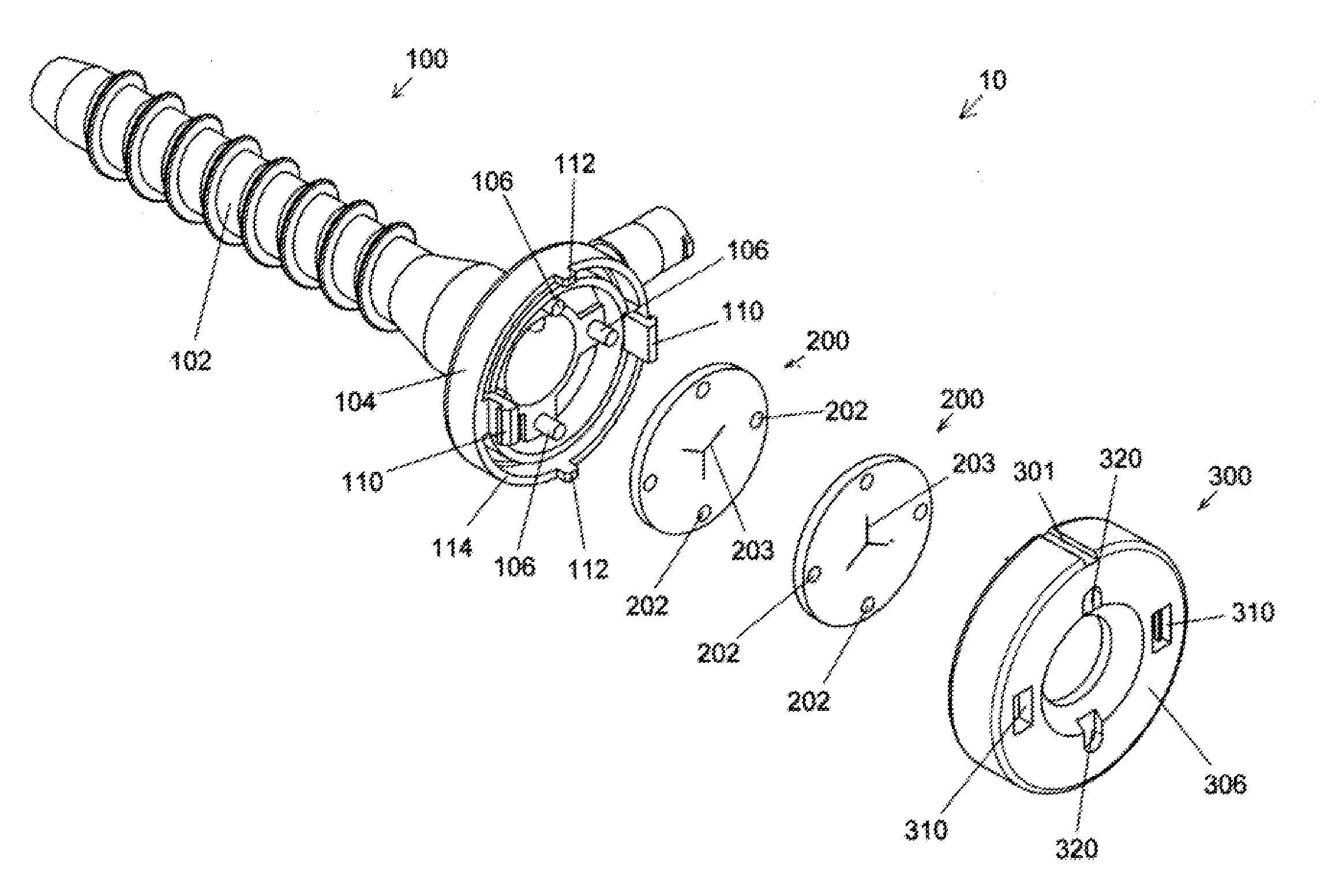
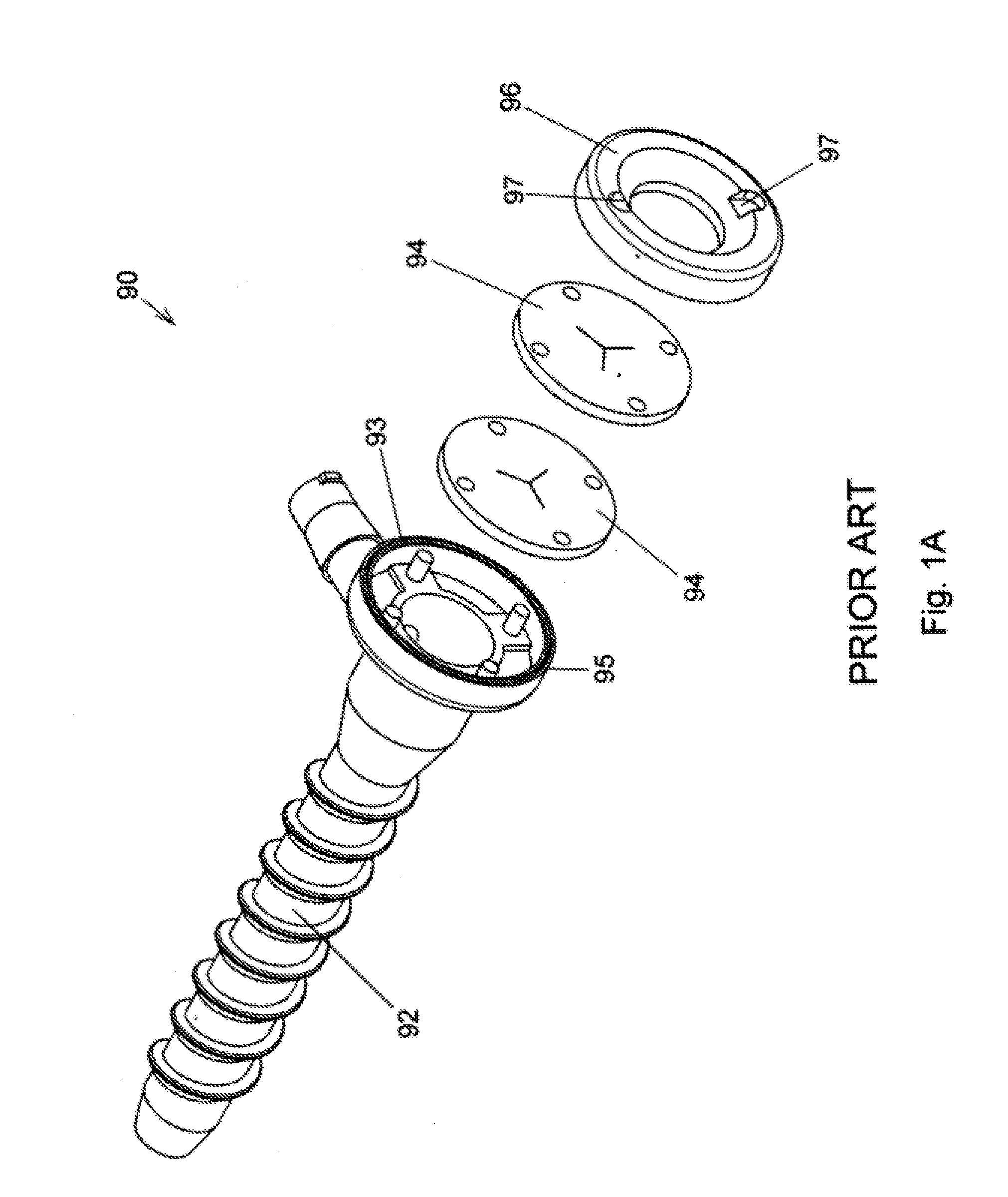
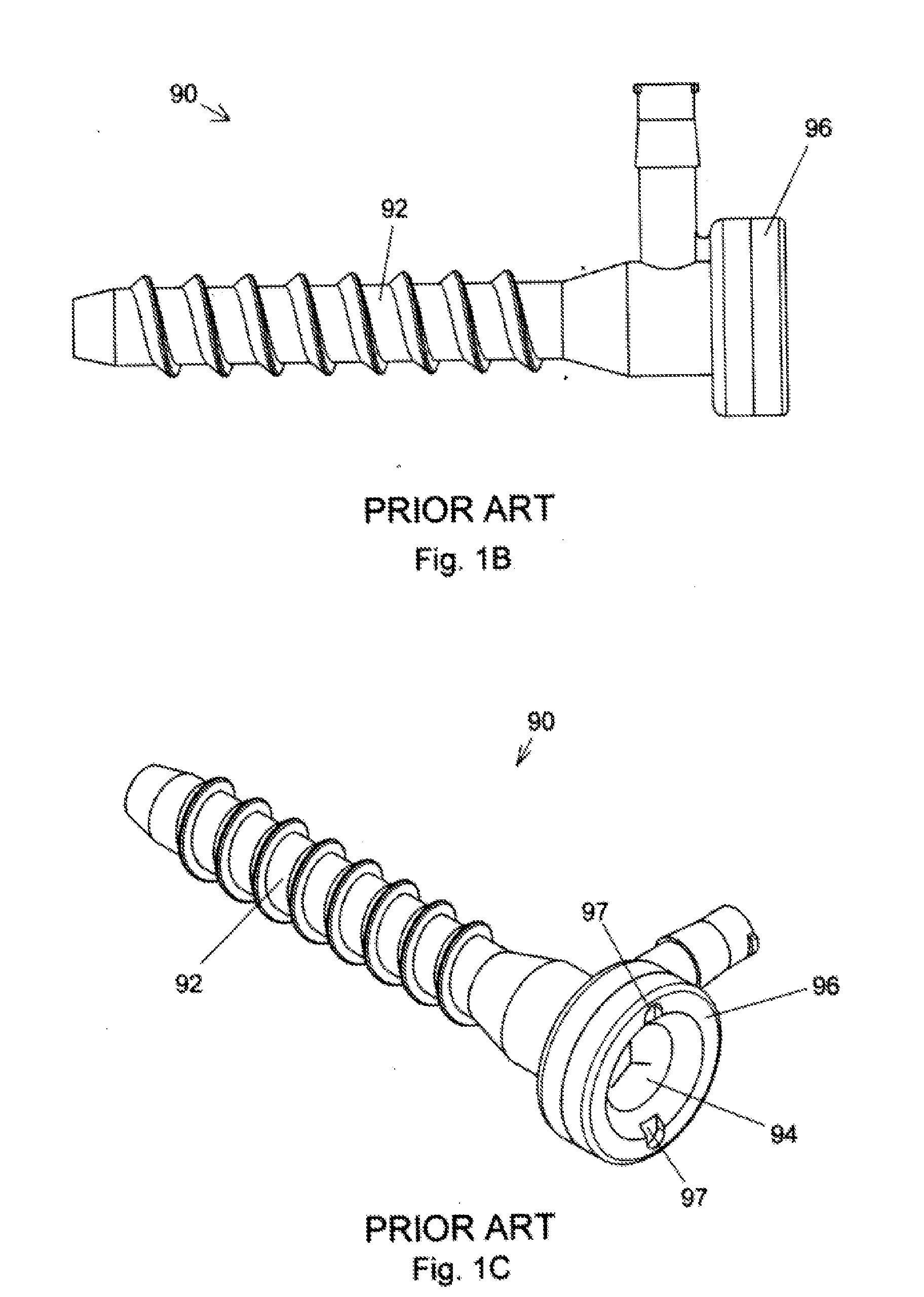
[0106]FIGS. 1A through 1C depict the construction of a typical prior art cannula, more particularly an arthroscopic sealing cannula. As best seen in FIG. 1A, prior art cannula 90 has a rigid polymeric distal element 92, one or more elastomeric membranes or seals 94, and a rigid polymeric proximal element 96 which is bonded to distal element 92 by ultrasonic welding, solvent bonding, or an adhesive, ultrasonic welding being the preferred method. Slots 97 in proximal element 96 allow cannula 90 to be inserted and retracted from a surgeon-formed portal in the body of a patient using a specialized handle called an obturator that allows the surgeon to apply axial force and torque to cannula 90 as needed. Cannula 90 as shown is configured for assembly by ultrasonic welding of distal portion 92 to proximal portion 96 with proximal facing annular surface 93 having formed thereon an annular ridge 95 which functions as an “energy director” to aid in forming the bond. When subjected to pressur...


PUM


Abstract

An arthroscopic sealing cannula having improved efficiency, access and reduced manufacturing costs is described herein. In particular, the present invention describes arthroscopic sealing cannulae in which the conventional thermal and chemical bonding means are eliminated and replaced with a mechanical joining system that utilizes mating fastener pairs integrally molded into the distal and proximal elements of a cannula so as to thereby provide a strong reliable joining of the elements. Such a mechanical system eliminates the need for costly capital equipment and specializing tooling as well as the material and environmental handling problems associated with conventional bonding techniques. Furthermore, in that the join may be readily confirmed through simple visual examination, the present invention also eliminates the need for complex, costly, and time-consuming validation procedures mandated by regulations in place to ensure proper integrity, strength, and reliability of the bond. Accordingly, arthroscopic sealing cannulae constructed in accordance with the principles of this invention are expected to have increased reliability and reduced manufacturing costs.

Description

PRIORITY[0001]This application claims the benefit of U.S. Provisional Application No. 61 / 959,557 filed Aug. 27, 2013. The entire content of this priority application is incorporated by reference herein.FIELD OF THE INVENTION[0002]The present invention relates to an efficient and simplified cannula for endoscopic surgery.BACKGROUND OF THE INVENTION[0003]Arthroscopic procedures generally involve the passage of elongated instruments through portals that facilitate access to the internally located surgery site. Because these sites are generally filled with liquid under pressure, the use of a sealing access device is required. It is required that this access device, commonly called a sealing cannula or simply a cannula, provide for easy insertion, manipulation and retraction of instruments, and while also maintaining a fluid seal to prevent uncontrolled escape of pressurized fluid from the site. This sealing must be maintained both when instruments are in use as well as when there are no...

Claims


Application Information

Patent Timeline
Patent Type & Authority Applications(United States)
IPC IPC(8): A61B17/34A61B17/02
CPCA61B17/0218A61B17/3423A61B17/3462A61B17/3417A61B2017/00477A61B2017/2905A61B2017/349
Inventor VAN WYK, ROBERT A.HEISLER, GARY R.
Owner HANSHI
Why Eureka
Try Eureka