Biomass-mixed, pulverized coal-fired burner and fuel combustion method

a technology of pulverized coal and biomass, which is applied in the direction of combustion types, lighting and heating apparatus, incinerator apparatus, etc., can solve the problems of not being able to supply biomass material at the moment, and achieve the effect of reducing nox, facilitating ignition of the burner and holding the flame, and large reverse flow rang

Active Publication Date: 2015-03-12
KAWASAKI HEAVY IND LTD
View PDF8 Cites 15 Cited by
  • Summary
  • Abstract
  • Description
  • Claims
  • Application Information

AI Technical Summary

Benefits of technology

[0024]The pulverized coal fuel jet nozzle includes a pulverized coal fuel conveying pipe that forms a flow path for the pulverized coal fuel stream, a pulverized coal fuel swirl vane that converts the pulverized coal fuel stream to a swirl flow whirling around an outer circumference of the biomass fuel jet nozzle to thereby make a fuel concentration lower on an axis side of the pulverized coal fuel conveying pipe and higher on an outer circumferential wall side of the pulverized coal fuel conveying pipe, a flame stabilizer having a funnel-shaped opening at a pipe end of the pulverized coal fuel jet port, and a pulverized coal fuel baffle plate disposed on a pipe inner wall upstream of the flame stabilizer, the pulverized coal fuel baffle plate reducing a swirl of the pulverized coal fuel stream jetted from the pulverized coal fuel jet port.
[0034]Furthermore, a biomass-mixed, pulverized coal-fired boiler to which the biomass-mixed, pulverized coal-fired burner according to the aspect of the present invention is applied can reduce coal consumption, the amount of NOx in exhaust gases, and the amount of CO2 emissions originated from fossil fuels through the use of the biomass fuel as the auxiliary fuel.

Problems solved by technology

Unfortunately, however, a supply of the biomass material is not necessarily steady currently.

Method used


Image

  • Biomass-mixed, pulverized coal-fired burner and fuel combustion method
  • Biomass-mixed, pulverized coal-fired burner and fuel combustion method
  • Biomass-mixed, pulverized coal-fired burner and fuel combustion method

Examples


Embodiment Construction

[0038]An embodiment of the present invention will be described below with reference to the accompanying drawings.

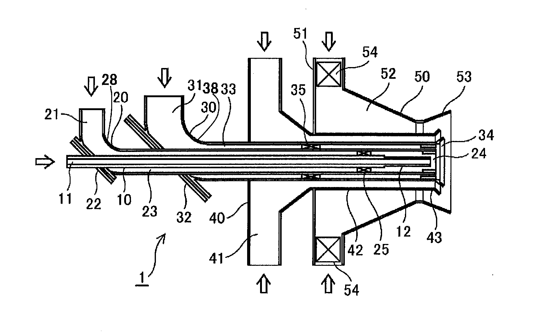
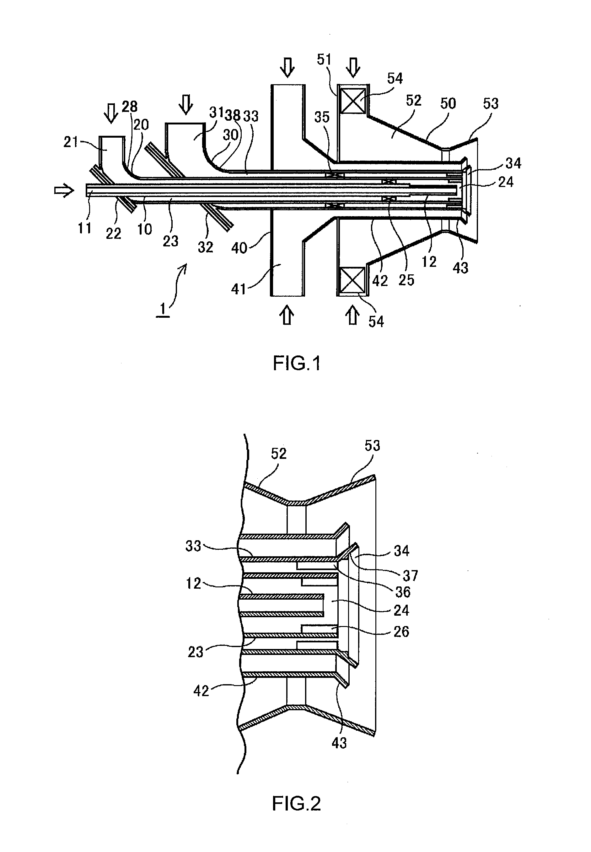
[0039]FIG. 1 is a schematic cross-sectional view showing a biomass-mixed, pulverized coal-fired burner according to an embodiment of the present invention. FIG. 2 is an enlarged cross-sectional view showing a jet port portion of the burner according to the embodiment.

[0040]Reference is made to FIG. 1. The biomass-mixed, pulverized coal-fired burner 1 according to the embodiment includes a biomass fuel jet nozzle 20 disposed at a center thereof. The biomass-mixed, pulverized coal-fired burner 1 further includes a pulverized coal fuel jet nozzle 30, a secondary air nozzle 40, and a tertiary air nozzle 50 disposed coaxially in sequence around the biomass fuel jet nozzle 20. It is noted that an auxiliary fuel nozzle 10 that supplies auxiliary or starting liquid or gas fuel may be disposed on a pipe axis of the biomass fuel jet nozzle 20.

[0041]The biomass fuel jet nozzle 20 su...


PUM


Abstract

A biomass-mixed, pulverized coal-fired burner is provided. The biomass-mixed, pulverized coal-fired burner is capable of burning biomass fuel as auxiliary fuel in large quantities and burning only pulverized coal when the biomass fuel is not sufficiently available. The biomass-mixed, pulverized coal-fired burner includes: a biomass fuel jet nozzle that extends axially along the biomass-mixed, pulverized coal-fired burner; a pulverized coal fuel jet nozzle that surrounds the biomass fuel jet nozzle; a secondary air nozzle that surrounds the pulverized coal fuel jet nozzle; and a tertiary air nozzle that surrounds the secondary air nozzle. A biomass fuel stream is jetted into an inside of a pulverized coal fuel flame formed in a furnace, the flame offering favorable ignition and flame holding performance.

Description

TECHNICAL FIELD[0001]The present invention relates to a biomass-mixed, pulverized coal-fired burner that burns biomass fuel together with pulverized coal in a mixed state and to a fuel combustion method.BACKGROUND ART[0002]Recently, a need exists to promote planned performance of steps against global warming. Of the total greenhouse effect gases discharged in Japan, energy-derived CO2 emissions account for about 90% in recent years. Moreover, of the total power generated, coal-fired power plant discharges 50% CO2. Thus, coal-fired power plants are required to promote the use of new types of energy having low environmental impact.[0003]Organic substances repeat a cycle of decomposition, absorption, and release. Equilibrium can thus be achieved for the amount of CO2 discharged by biomass energy by having a source of absorbing the equal amount of CO2. In this way, biomass is a carbon neutral fuel and thus biomass power generation carries the weight of expectations as new energy, which ...

Claims


Application Information

Patent Timeline
Patent Type & Authority Applications(United States)
IPC IPC(8): F23C1/00F23D17/00F23G7/10F23D1/00
CPCF23C1/00F23G7/10F23D17/00F23D1/005F23C6/045F23C7/004F23D1/00F23C2201/20F23C2900/01001F23C2900/06041F23D2201/10F23D2201/20F23D2209/20
Inventor TANIGUCHI, KOJIKATO, ATSUNORIYABARA, SUGURUTANABE, YUTAKA
Owner KAWASAKI HEAVY IND LTD
Why Eureka
Try Eureka