Ventilator Apparatus and System of Ventilation

a technology of ventilator and apparatus, which is applied in the field of ventilator apparatus and ventilation system, can solve the problems of increasing respiratory frequency, increasing respiratory frequency, increasing frequency dependency, etc., and achieves the effect of facilitating the spontaneous breathing of the intubated patien

Inactive Publication Date: 2015-03-12
HABASHI NADER M
View PDF13 Cites 66 Cited by
  • Summary
  • Abstract
  • Description
  • Claims
  • Application Information

AI Technical Summary

Benefits of technology

[0038]Such valves can typically be included in line with the supply and exhaust ports and can be operable in cooperation with the various types of sensors discussed elsewhere herein. What are often referred to as back-check valves, which enable fluid flow in one direction but which prevent fluid flow in an opposite direction. Such check valves may be included in the gas circuit or network to protect various components and the patient from unexpected and / or undesirable pressures or pressure shock. In this way, protection can be afforded to the patient, pump or pressurized gas source, sensors, and other equipment.
[0065]Assuming for further purposes of illustration that the patient continues improving, then the command module changes ventilator operation again, and monitors P(high) until a CPAP threshold is reached, which enables another conversion of the ventilator operation into a CPAP sub-module. This sub-module is much more comfortable for patients, and reduces the dependence of the ventilator. As the further improvements are manifested, the command module begins to gradually reduce the CPAP pressure until an extubation threshold pressure is reached. Also, it may be optionally preferable during the CPAP and other modes of operation to enable the controller to incorporate an automatic tube compensation pressure or ATC pressure which boosts the ventilator support just enough to overcome the frictional losses encountered when breathing through the gas network or circuit of tubing involved in use of the ventilator.

Problems solved by technology

However, increased respiratory frequency is associated with increase lung injury.
Furthermore, increasing respiratory frequency increases frequency dependency and decreases potential to perform ventilation on the expiratory limb of the P-V curve.
Therefore, tidal volume reduction is unnecessary.
However, most patients with ALI / ARDS exhibit expiratory flow limitations.
Expiratory flow limitations results in dynamic hyperinflation and intrinsic positive end expiratory pressure (PEEP) development.
Pulmonary edema development and superimposed pressure result in increased airway closing volume and trapped volume.
In addition, the reduced number of functional lung units (derecruited lung units or alveolar and enhanced airway closure) decrease expiratory flow reserve further.
In addition, release from a sustained high lung volume increases stored energy and recoil potential, further accelerating expiratory flow rates.
Unlike low volume ventilation, release from a high lung volume increases airway caliber and reduces downstream resistance.
In ALI / ARDS, increased capillary permeability results in lung edema.
Dependent airspaces collapse and compressive atelectasis results in severe V / Q mismatching and shunting.
Increasing airway pressure can re-establish dependent transpulmonary pressure differential but at the risk of over distension of nondependent lung units.
However, spontaneous breathing during pressure support ventilation was not associated with improved V / Q matching in the dependent lung units.
The increased use of sedative and NMBA may increase the time the patient must remain on mechanical ventilation (“vent days”) and increase complications.
However, recent studies suggest that mechanical ventilation may produce, sustain or increase the risk of acute lung injury (ALI).
Animal data suggest that lung stress failure from VILI may result from high or low volume ventilation.
High volume stress failure is a type of stretch injury, resulting from over distension of airspaces.
In contrast, shear force stress from repetitive airway closure during the tidal cycle from mechanical ventilation results in low volume lung injury.
However, subsequent studies by Stewart and Brower were unable to demonstrate improved survival or ventilator free days utilizing low tidal volume ventilation strategy.
Such important differences between these studies limited conclusions as to the effectiveness of low tidal ventilation limiting ventilator associated lung injury (VALI).
The ARDSNet trial also failed to demonstrate any difference in the incidence of barotrauma.
The higher PEEP requirements and the potential for significant intrinsic PEEP from higher respiratory frequency in the lower tidal volume group, may have obscured potential contribution of elevated end expiratory pressure on survival.
Despite an increase in the knowledge of those skilled in the relevant arts as to how to improve and maintain recruitment which minimizes the possibility of VILI and other anomalies, the systems, devices, and methods of the prior remain difficult to operate and employ for use with the best practice protocols.
While due to many constraints, the often-cited challenges complained of by those skilled and practicing in the intensive care respiratory technical field is that a more automated and more accurate means is needed for applying the best practice APRV techniques.
Such manual adjustments often result in unfavorable patient response that results from inaccurate adjustments or adjustments that cannot be made with enough precision due to the constraints or limited capabilities of the presently available equipment.

Method used


Image

  • Ventilator Apparatus and System of Ventilation
  • Ventilator Apparatus and System of Ventilation
  • Ventilator Apparatus and System of Ventilation

Examples


Embodiment Construction

[0095]Referring now to the various figures and illustrations, those skilled in the relevant arts should appreciate that each of the preferred, optional, modified, and alternative embodiments of the inventive ventilator and ventilator system 10 and method of operation contemplate interchangeability with all of the various features, components, modifications, and variations within the scope of knowledge of those skilled in the relevant fields of technology and illustrated throughout the written description, claims, and pictorial illustrations herein.

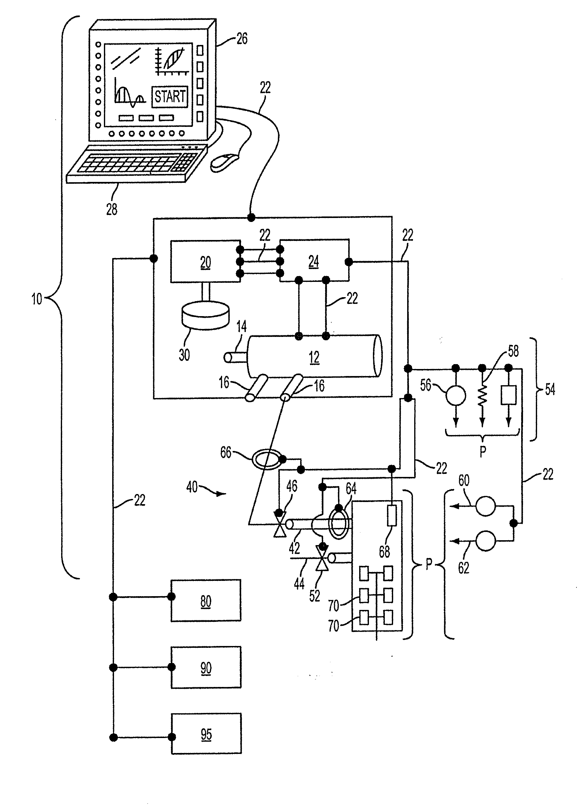
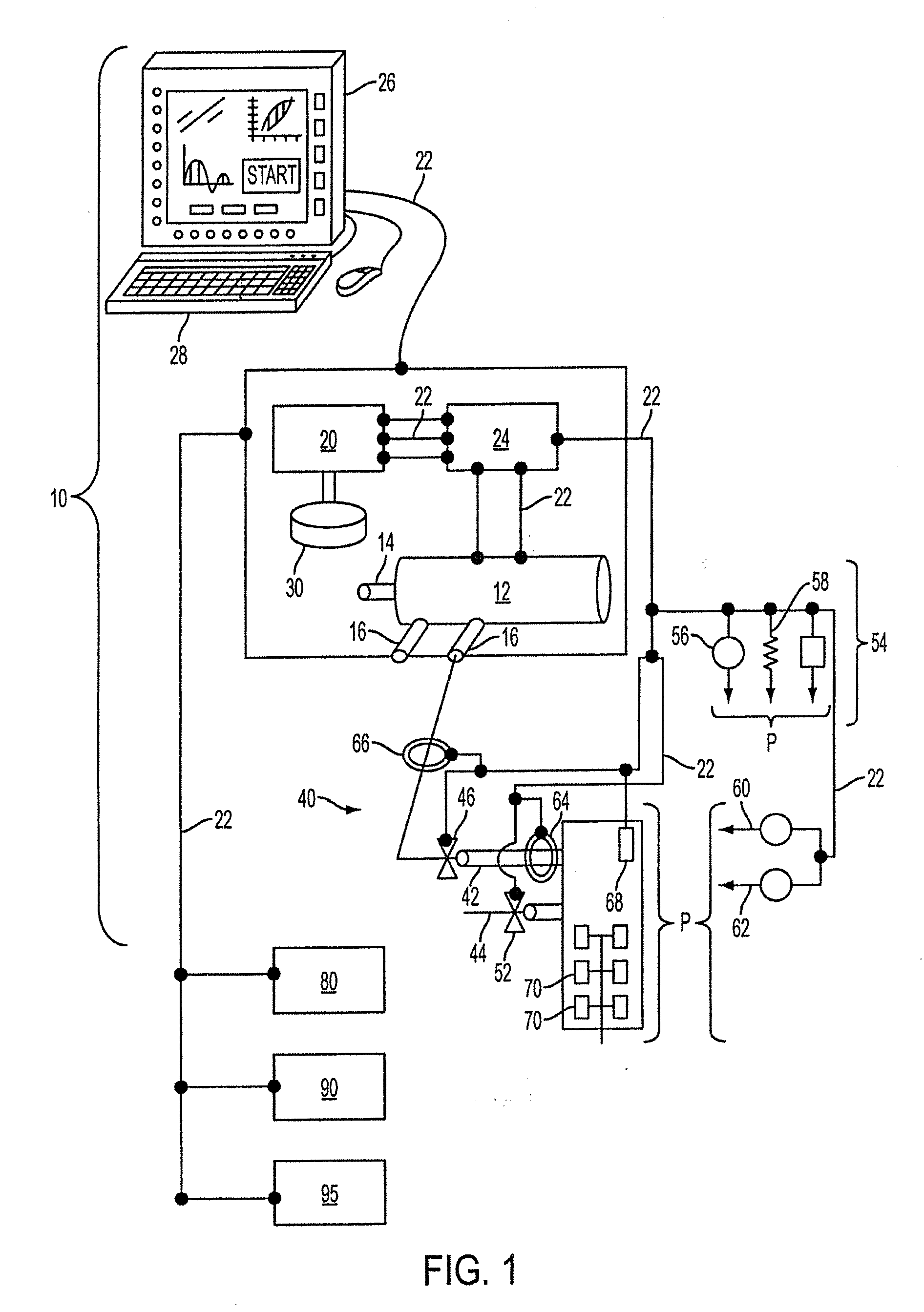
[0096]With this guiding concept in mind, and with reference now to FIG. 1, one possible embodiment of a ventilator and ventilator system 10 is illustrated, which is in communication with the patient P undergoing ventilation therapy. The ventilator and ventilator system 10 also preferably includes a gas supply pump and / or pressurized gas source 12 having a positive pressure port 14, and optionally a negative pressure port 16. The gas pump o...


PUM


Abstract

A ventilator for use by a clinician in supporting a patient presenting pulmonary distress. A controller with a touch-screen display operates a positive or negative pressure gas source that communicates with the intubated or negative pressure configured patient through valved supply and exhaust ports. A variety of peripheral, central, and / or supply / exhaust port positioned sensors may be included to measure pressure, volumetric flow rate, gas concentration, transducer, and chest wall breathing work. Innovative modules and routines are incorporated into the controller module enabling hybrid, self-adjusting ventilation protocols and models that are compatible with nearly every conceivable known, contemplated, and prospective technique, and which establish rigorous controls configured to rapidly adapt to even small patient responses with great precision so as to maximize ventilation and recruitment while minimizing risks of injury, atelectasis, and prolonged ventilator days.

Description

CROSS-REFERENCE TO RELATED APPLICATIONS[0001]This application is a continuation of U.S. patent application Ser. No. 12 / 131,922 filed Jun. 2, 2008, which claims priority to U.S. Provisional Patent Application No. 60 / 924,835 filed Jun. 2, 2007.BACKGROUND OF THE INVENTION[0002]1. Field of the Invention[0003]The invention relates to the field of ventilating human patients. More particularly, the present invention relates to an improved ventilator and method of operation for ventilation intervention and initiation, oxygenation, recruitment, ventilation, initial weaning, airway pressure release ventilation weaning, continuous positive airway pressure weaning, and continuous and periodic management and control of the ventilator.[0004]2. Description of Related Art[0005]The inventor herein has previously invented, among other inventions, ventilator systems and methods of operation disclosed and claimed in U.S. Pat. No. 7,246,618, and in U.S. Patent Application Nos. 2008 / 0072901, 2006 / 0174884...

Claims


Application Information

Patent Timeline
Patent Type & Authority Applications(United States)
IPC IPC(8): A61M16/00A61M16/10A61M16/20A61M16/06
CPCA61M16/0069A61M2205/52A61M16/0051A61M16/0666A61M16/1005A61M16/208A61M2016/0027A61M2016/003A61M2016/1025A61M2016/103A61M2205/18A61M2205/3334A61M2205/3327A61M2205/505A61M16/0003A61M2016/0021A61M2016/0039A61M2016/0042A61M2205/3561A61M2205/3592A61M2230/202A61M2230/205A61M2230/42A61M2230/432A61M2230/435A61M2230/60A61M16/024A61M2230/005
Inventor HABASHI, NADER
Owner HABASHI NADER M
Why Eureka
Try Eureka