Inverter and direct current bus voltage regulating method thereof and application using the same

a technology of direct current and bus voltage, applied in the direction of electric variable regulation, process and machine control, instruments, etc., can solve the problems of low conversion efficiency of inverter, difficult to maintain dc bus voltage stable, etc., and achieve the effect of improving conversion efficiency

Active Publication Date: 2015-03-12
FSP POWERLAND TECH +1
View PDF5 Cites 4 Cited by
  • Summary
  • Abstract
  • Description
  • Claims
  • Application Information

AI Technical Summary

Benefits of technology

[0008]The invention is directed to an inverter and a direct current (DC) bus voltage regulating method thereof, which is capable of providing a stable DC bus voltage capable of being dynamically adjusted, so as to improve conversion efficiency.
[0021]According to the above descriptions, the embodiment of the invention provides an inverter a DC bus voltage regulating method thereof. The inverter regulates the DC input voltage by using the hysteresis control means, such that the resonant conversion circuit of the inverter does not influence the voltage value of the generated DC bus voltage along with a disturbance or a tiny variation of the DC input voltage, so as to improve stability of DC-AC conversion of the post-stage inverting circuit.

Problems solved by technology

However, since a magnitude of the DC bus voltage is actually varied along with variation of a DC input voltage received by the DC-DC conversion circuit, in some applications (for example, a photovoltaic grid-connected system), it is not easy to maintain the DC bus voltage stable.
Moreover, if only the DC bus voltage is designed to the constant voltage value, the inverter may have low conversion efficiency when the constant voltage value is far greater than the DC bus voltage required by the post-stage inverting circuit.

Method used


Image

  • Inverter and direct current bus voltage regulating method thereof and application using the same
  • Inverter and direct current bus voltage regulating method thereof and application using the same
  • Inverter and direct current bus voltage regulating method thereof and application using the same

Examples


Embodiment Construction

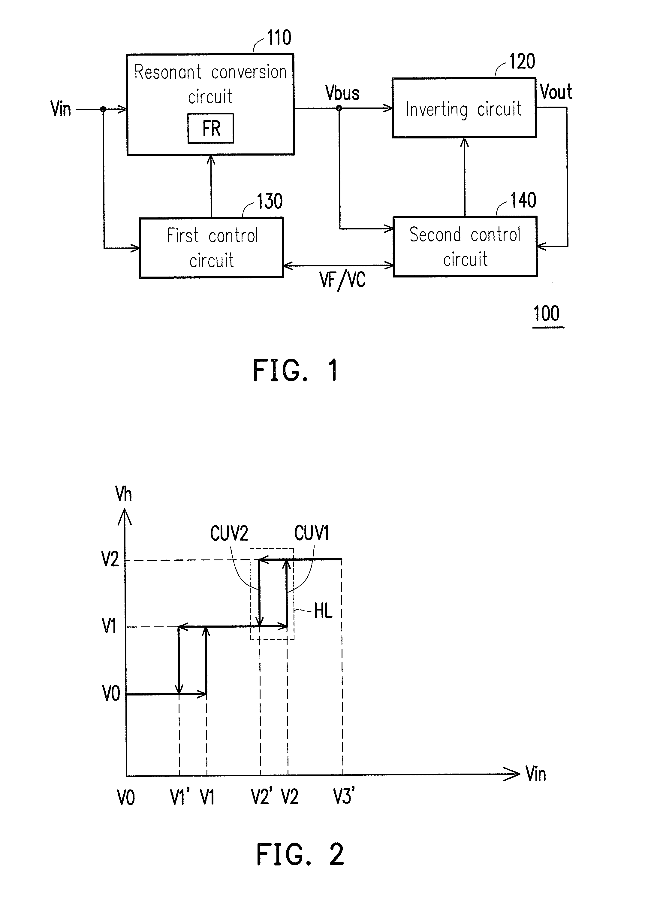
[0030]Embodiments of the invention provide an inverter a DC bus voltage regulating method thereof. The inverter regulates a DC input voltage by using a hysteresis control means, such that the resonant conversion circuit of the inverter does not influence a voltage value of a generated DC bus voltage along with a disturbance or a tiny variation of the DC input voltage, so as to improve stability of DC-AC conversion of the post-stage inverting circuit. Reference will now be made in detail to the present preferred embodiments of the invention, examples of which are illustrated in the accompanying drawings. Wherever possible, the same reference numbers are used in the drawings and the description to refer to the same or like parts.

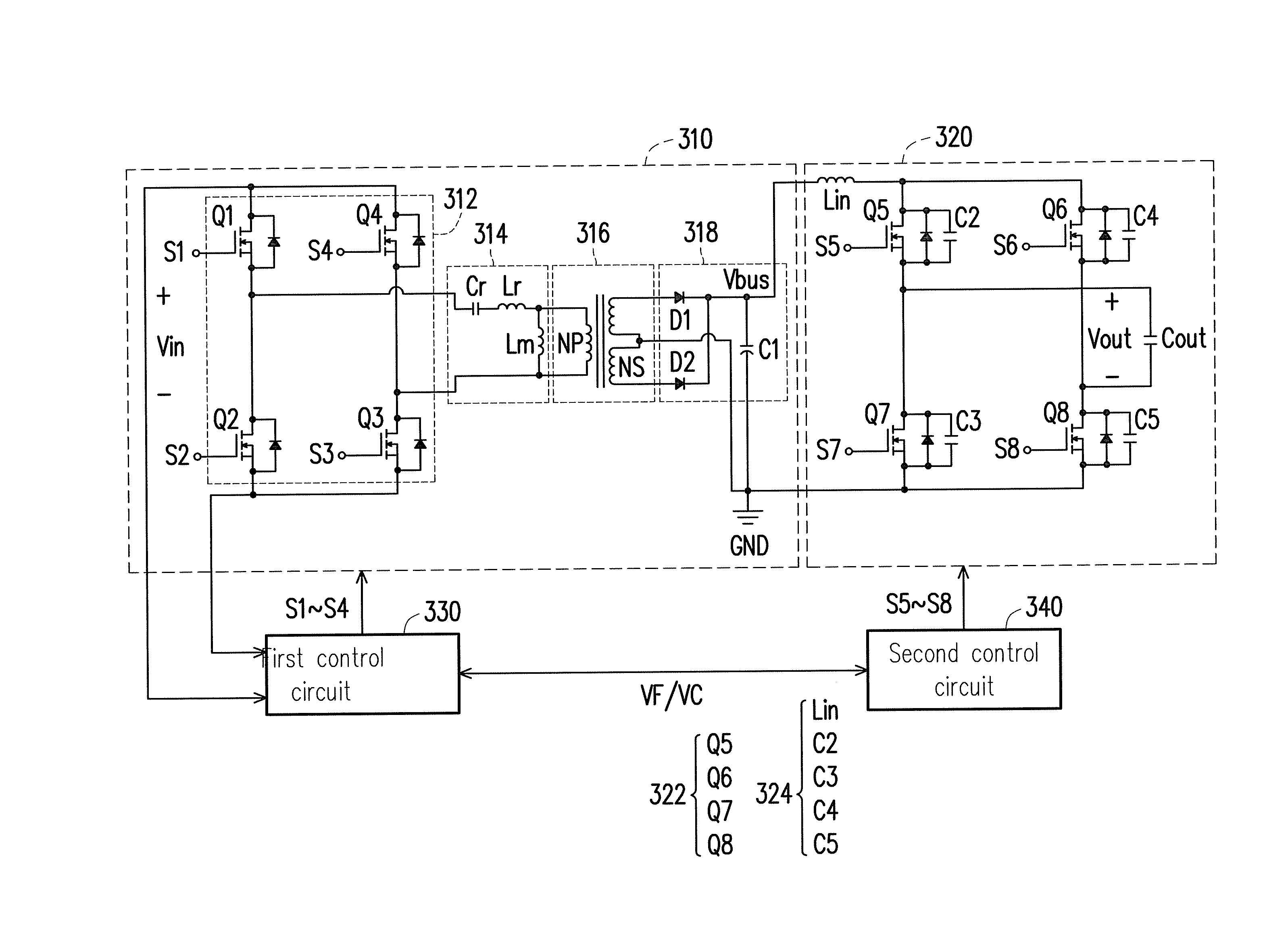
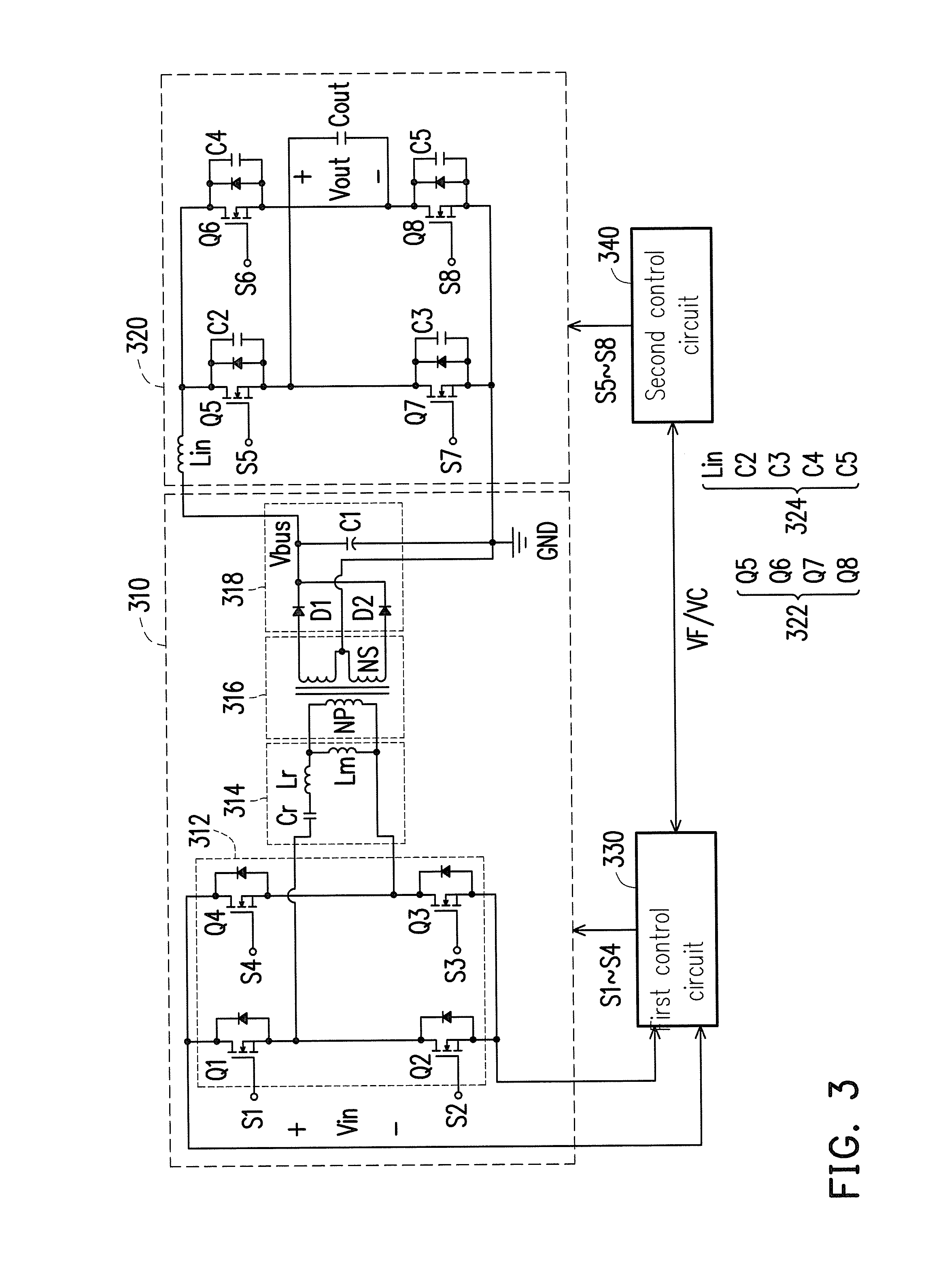
[0031]FIG. 1 is a schematic diagram of an inverter according to an embodiment of the invention. Referring to FIG. 1, the inverter 100 of the present embodiment includes a resonant conversion circuit 110, an inverting circuit 120, a first control circuit 130 an...


PUM


Abstract

An inverter and a direct current (DC) bus voltage regulating method thereof are provided. The inverter includes a resonant conversion circuit, an inverting circuit, a first control circuit and a second control circuit. The resonant conversion circuit receives a DC input voltage and converts the same into a DC bus voltage. The inverting circuit couples to the resonant conversion circuit, and configured to convert the DC bus voltage into an AC output voltage. The first control circuit is configured to control operations of the resonant conversion circuit, where the first control circuit calculates a best working voltage of the resonant conversion circuit based on the DC input voltage and a resonant frequency of the resonant conversion circuit. The second control circuit controls operations of the inverting circuit, where the second control circuit receives the best working voltage calculated by the first control circuit and regulates the DC bus voltage accordingly.

Description

CROSS-REFERENCE TO RELATED APPLICATION[0001]This application claims the priority benefit of China application serial no. 201310406115.6, filed on Sep. 9, 2013. The entirety of the above-mentioned patent application is hereby incorporated by reference herein and made a part of this specification.BACKGROUND[0002]1. Technical Field[0003]The invention relates to a power conversion technique. Particularly, the invention relates to an inverter and a direct current bus voltage regulating method thereof.[0004]2. Related Art[0005]In design of a general inverter, a basic condition for implementing a normal operation of the inverter is that an amplitude of a direct current (DC) bus voltage is not smaller than a peak of an alternating current (AC) output voltage. In other words, regarding the inverter adopting a multistage conversion circuit configuration, especially a two-stage inverter composed of a DC-DC conversion circuit and an inverting circuit, in order to ensure a normal operation of th...

Claims


Application Information

Patent Timeline
Patent Type & Authority Applications(United States)
IPC IPC(8): H02M7/5387H02M3/335H02M1/00
CPCH02M3/33507H02M7/53871H02M3/3376H02M1/0058H02M1/007Y02B70/10H02M7/4826
Inventor MU, JIAN-GUOWANG, CHUAN-YUNXU, MING
Owner FSP POWERLAND TECH
Why Eureka
Try Eureka