Synchronized rotating arc welding method and system

a rotating arc welding and synchronized technology, applied in the field of welding techniques, can solve the problems of inert shielding gases, common divisions between welding apparatuses, and relatively high cost, and achieve the effects of increasing the success rate of welded pieces, speeding up the overall manufacturing process, and increasing the speed of processes

Active Publication Date: 2015-03-19
ILLINOIS TOOL WORKS INC
View PDF7 Cites 39 Cited by
  • Summary
  • Abstract
  • Description
  • Claims
  • Application Information

AI Technical Summary

Benefits of technology

[0007]Manufacturers are constantly looking for new ways to improve automated welding methods, increase the success rate of the welded pieces, and speed up the manufacturing process overall. However, current automated welding techniques coupled with the increased speed of the processes that manufacturers have come to rely on can result in many finished workpieces with poor fit-up.
[0008]In one embodiment, a welding method includes feeding a welding electrode axially from a welding torch, moving the welding electrode radially in a desired pattern with respect to a central axis of the welding torch by a motion control assembly within the welding torch, transmitting from control circuitry a signal corresponding to a position of the welding electrode relative to a weld joint or weld pool, advancing the welding torch or a workpiece to establish a weld, and transferring material from the welding electrode to a first location in an area of the weld pool. The welding electrode moves radially while feeding the welding electrode from the welding torch, the material from the welding electrode is transferred to the first location during a first cycle of the desired pattern, and the first location is controlled based at least in part on the signal.
[0009]In another embodiment, a welding method includes feeding a welding electrode axially from a welding torch, moving the welding electrode radially in a desired movement pattern with respect to a central axis of the welding torch by a motion control assembly within the welding torch, transmitting from control circuitry a signal corresponding to a position of the welding electrode within the desired movement pattern, advancing the welding torch or a workpiece to establish a weld, and controlling a heat pattern applied to at least one of the workpiece and an area of a weld pool based at least in part on the signal. The welding electrode moves radially while feeding the welding electrode from the welding torch.
[0010]In another embodiment, a welding method includes establishing an arc between a welding electrode and a workpiece, feeding the welding electrode from a welding torch while moving the welding electrode in a desired pattern with respect to a central axis of the welding torch at a radial movement rate between approximately 5 Hz and 200 Hz by a motion control assembly within the welding torch, advancing the welding torch or a workpiece to establish a weld, detecting a fit-up condition of the workpiece via monitoring changes in a weld current, a weld voltage, an arc voltage, or a contact tip to work distance, and controlling one or more welding parameters based at least in part on a position of the welding electrode within the desired pattern and the detected fit-up condition while maintaining the arc. The one or more welding parameters includes at least one of the radial movement of the welding electrode in the desired pattern, a parameter of the welding power applied to the welding electrode, a welding torch travel speed, a welding torch travel angle, and a welding torch angle.

Problems solved by technology

However, further divisions between these are common, particularly in processes that consume an electrode to add filler metal to the weld.
For example, solid wire, while less expensive than the other types, is typically used with inert shielding gases, which can be relatively expensive.
Flux cored wires may not require separate shielding gas feeds, but are more expensive than solid wires.
Depending on the fit-up between the workpieces, the weld bead width may or may not be adequate to ensure the integrity of the finished welded product.
However, automated welding systems lack this intelligent consideration and may not be tolerant of fit-up gaps beyond a narrow tolerance range.
Moreover, excess heat applied to relatively thin portions of the workpieces and / or to the weld bead may form holes in the weld bead.
This may result in weld defects, manual reworking, and ultimate rejection of finished welded parts.
However, current automated welding techniques coupled with the increased speed of the processes that manufacturers have come to rely on can result in many finished workpieces with poor fit-up.

Method used


Image

  • Synchronized rotating arc welding method and system
  • Synchronized rotating arc welding method and system
  • Synchronized rotating arc welding method and system

Examples


Embodiment Construction

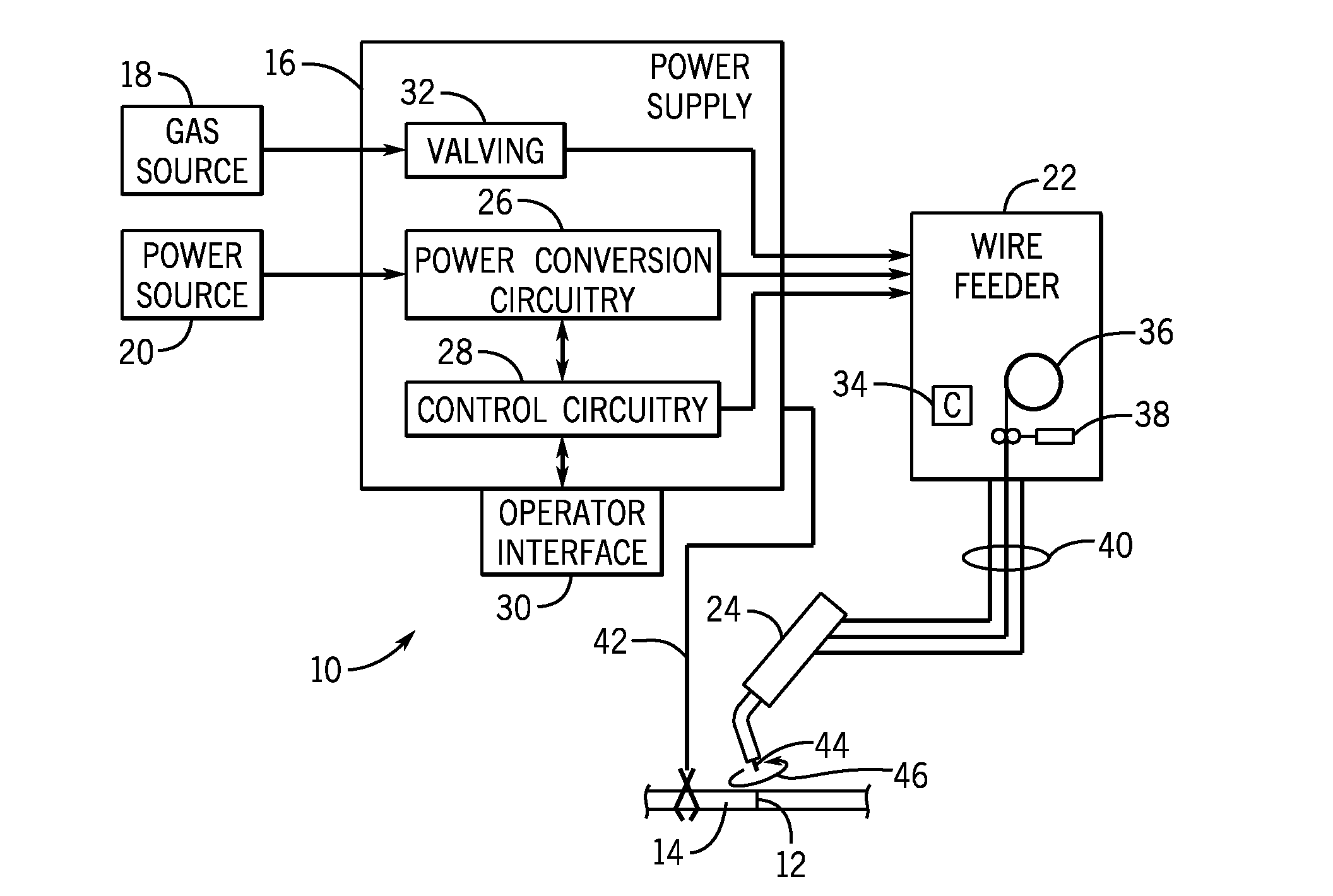
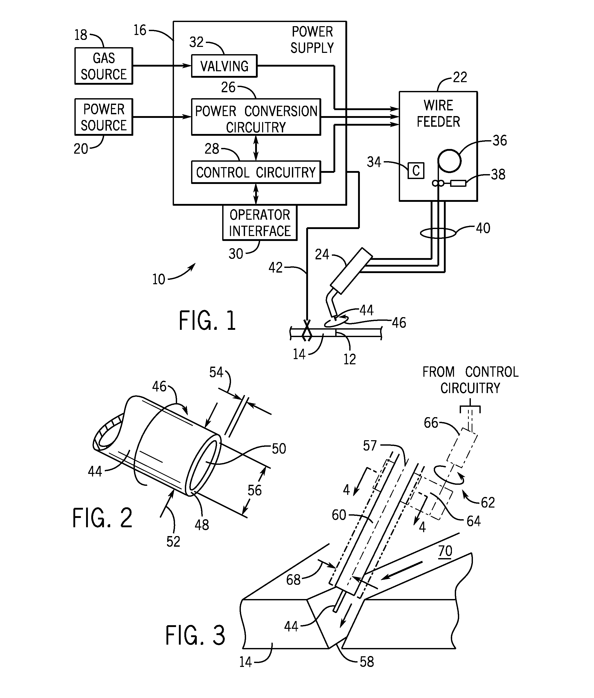
[0036]FIG. 1 illustrates an exemplary welding system 10 utilizing movement of a metal cored welding wire electrode though as discussed earlier these techniques could be used with many types of wires, such as solid wire or flux cored wire. The system 10 is designed to produce a weld 12 on a workpiece 14. The weld may be oriented in any desired manner, including butt weld, lap weld, angled welds, out-of-position welds, and so forth. The system includes a power supply 16 that will typically be coupled to a gas source 18 and to a power source 20, such as the power grid. Other power sources, of course, include generators, engine-driven power packs, and so forth. A wire feeder 22 is coupled to the power supply 16 and supplies the metal cored welding wire to a welding torch 24.

[0037]In the illustrated embodiment, the power supply 16 will include power conversion circuitry 26 coupled to control circuitry 28 that regulates operation of the power conversion circuitry to produce power output s...


PUM

PropertyMeasurementUnit
diametersaaaaaaaaaa
diametersaaaaaaaaaa
lengthaaaaaaaaaa

Abstract

A welding method includes feeding a welding electrode axially from a welding torch, moving the welding electrode radially in a desired pattern with respect to a central axis of the welding torch by a motion control assembly within the welding torch, transmitting from control circuitry a signal corresponding to a position of the welding electrode relative to a weld joint or weld pool, advancing the welding torch or a workpiece to establish a weld, and transferring material from the welding electrode to a first location in an area of the weld pool. The welding electrode moves radially while feeding the welding electrode from the welding torch, the material from the welding electrode is transferred to the first location during a first cycle of the desired pattern, and the first location is controlled based at least in part on the signal.

Description

CROSS-REFERENCE TO RELATED APPLICATIONS[0001]This application claims priority from and the benefit of U.S. Provisional Application Ser. No. 61 / 878,404, entitled “SYNCHRONIZED ROTATING ARC WELDING METHOD AND SYSTEM,” filed Sep. 16, 2013, which is hereby incorporated by reference in its entirety for all purposes.BACKGROUND[0002]The invention relates generally to welding techniques, and more particularly to improved automated welding processes. The present disclosure is related to previously filed U.S. patent application Ser. No. 13 / 767,392, entitled “Adaptable Rotating Arc Welding Method and System,” filed on Feb. 14, 2013, which is hereby incorporated into the present disclosure by reference. The present disclosure also incorporates U.S. patent application Ser. No. 13 / 526,278, entitled “Metal Cored Welding Method and System,” filed on Jun. 18, 2012, and U.S. patent application Ser. No. 13 / 681,687, entitled “DC Electrode Negative Rotating Arc Welding Method and System,” filed on Nov. ...

Claims


Application Information

Patent Timeline
Patent Type & Authority Applications(United States)
IPC IPC(8): B23K9/095B23K9/173B23K9/16
CPCB23K9/0956B23K9/173B23K9/164B23K9/0216B23K9/0953
Inventor HSU, CHRISTOPHERHUTCHISON, RICHARD MARTINSCOTT, KEVIN MICHAELPAGANO, KEVINUECKER, JAMES LEE
Owner ILLINOIS TOOL WORKS INC
Why Eureka
Try Eureka