Arrangement to reduce noise emission

a technology of noise reduction device and noise level, which is applied in the direction of liquid fuel engine, vessel construction, marine propulsion, etc., can solve the problems of limited rotor diameter and noise emission level, and achieve the reduction of noise reduction device self-noise, reduced drag, and reduced mean flow speed

Inactive Publication Date: 2015-03-19
SIEMENS AG
View PDF8 Cites 28 Cited by
  • Summary
  • Abstract
  • Description
  • Claims
  • Application Information

AI Technical Summary

Benefits of technology

[0014]An advantage of locating the noise reduction device inside the boundary layer is that drag is lower and that possible self-noise from the noise reduction device is reduced due to a reduced mean flow speed.
[0015]An advantage of locating the noise reduction shield outside of the boundary layer is that the complete boundary layer is shielded and that possible self-noise from the noise reduction device is reduced due to lower turbulence outside the boundary layer.
[0016]A general advantage of the noise reduction device is that the noise reduction device may function as an additional airfoil at low wind speeds when the boundary layer is thin. This is due to the fact that the noise reduction device extends outside the boundary layer where the noise reduction device is aerodynamically active. Thus, a higher power generated by the wind turbine under operation is possible at low wind speeds compared to a wind turbine rotor blade without a noise reduction device.

Problems solved by technology

This is due to the fact that the noise emission level of a wind turbine sets a limitation on if a wind turbine is allowed to be built and how close in the proximity of residential areas the wind turbine is allowed to be built.
Thus, the noise emission level may set a limitation to a rotational frequency of a rotor of the wind turbine because of the above mentioned restrictions.
Furthermore, also the rotor diameter may be limited by noise constraints.

Method used


Image

  • Arrangement to reduce noise emission
  • Arrangement to reduce noise emission
  • Arrangement to reduce noise emission

Examples


Embodiment Construction

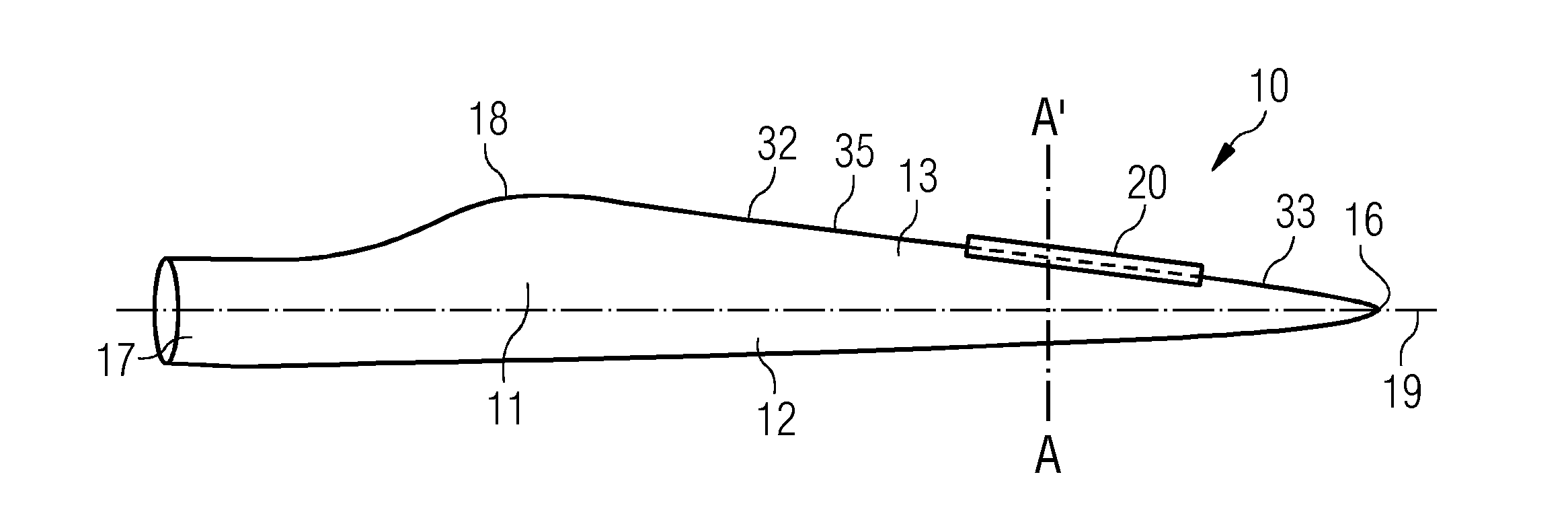
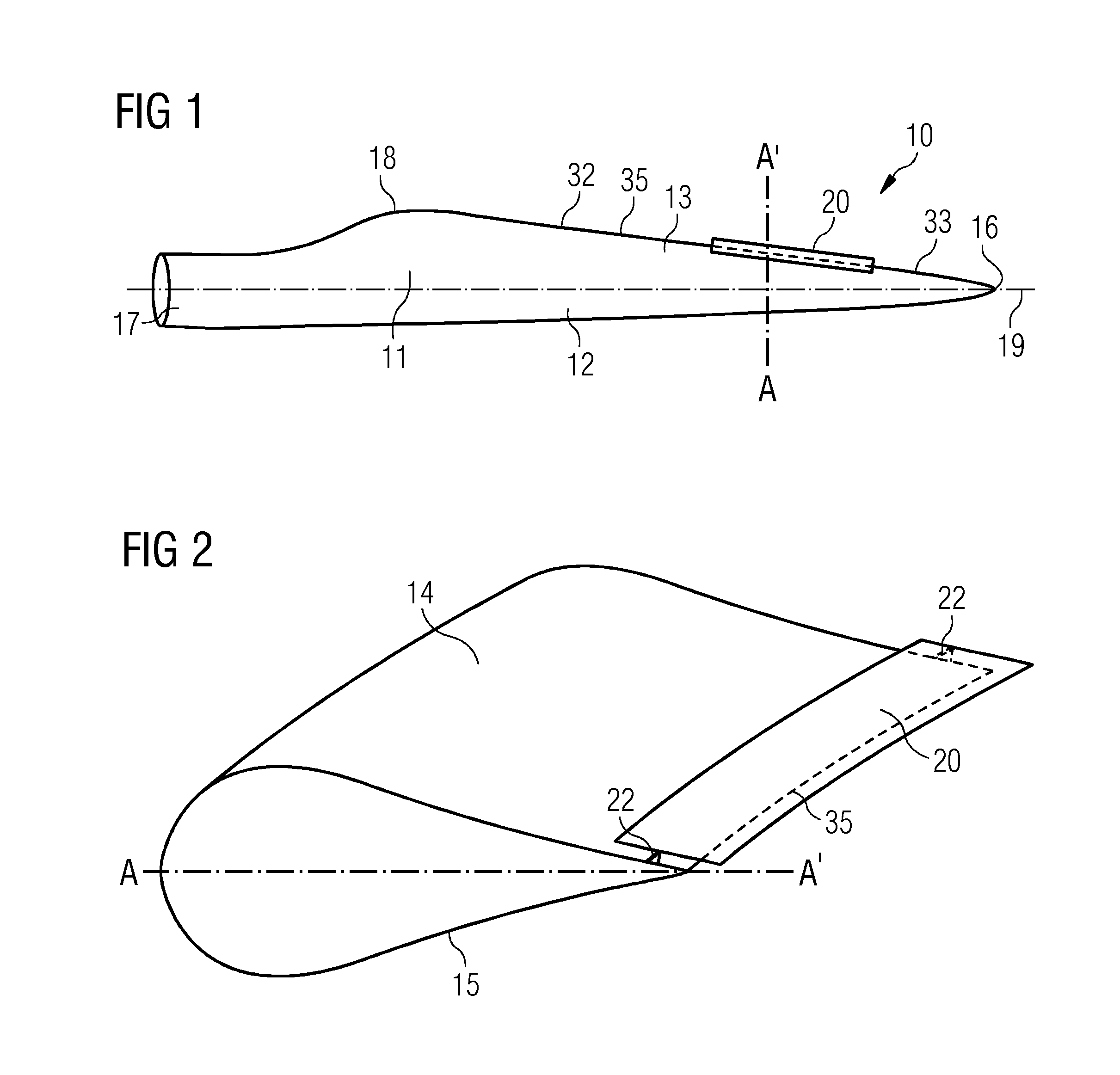
[0063]FIG. 1 shows an arrangement 10 to reduce noise emission, which is generated by a wind turbine rotor blade 11. The arrangement 10 comprises a wind turbine rotor blade 11 and a noise reduction device 20. The wind turbine rotor blade 11 comprises a root 17 and a tip end 16. The root 17 and the tip end 16 are virtually connected by a rotor blade longitudinal axis 19. Furthermore, the wind turbine rotor blade 11 comprises a rotor blade leading edge section 12 and rotor blade trailing edge section 13. The rotor blade trailing edge section 13 comprises a rotor blade trailing edge 35. The rotor blade trailing edge 35 has to be understood as an edge or a rim or a line, while the rotor blade trailing edge section 13 and the rotor blade leading edge section 12 each has to be understood as a section or a region or an area of the wind turbine rotor blade 11. The rotor blade trailing edge 35 extends from a shoulder 18 of the wind turbine rotor blade 11 to the tip end 16. The rotor blade tra...


PUM

PropertyMeasurementUnit
angleaaaaaaaaaa
angleaaaaaaaaaa
angleaaaaaaaaaa

Abstract

An arrangement to reduce noise emission generated by a wind turbine rotor blade is provided. The arrangement includes the rotor blade and a noise reduction device attached thereto. The rotor blade has a suction side and pressure side, leading and trailing edge sections with a trailing edge. The noise reduction device has an inner surface facing the rotor blade trailing edge section, and an outer surface opposite to the inner surface. The noise reduction device has a leading and trailing edge, both connecting the inner and outer surface. The noise reduction device is connected at the rotor blade trailing edge section by a connector. The inner surface has a pre-defined distance to at least one side of the rotor blade chosen so acoustic waves generated at the rotor blade trailing edge section are reflected by the inner surface to reduce noise emission generated by the wind turbine rotor blade.

Description

CROSS REFERENCE TO RELATED APPLICATIONS[0001]This application claims priority to and the benefit of European Application No. EP13184993 filed Sep. 18, 2013, incorporated by reference herein in its entirety.FIELD OF INVENTION[0002]The present invention relates to an arrangement to reduce noise emission, the noise emission being generated by a wind turbine rotor blade. In particular, the arrangement comprises a noise reduction device, which is connected to the wind turbine rotor blade at a rotor blade trailing edge section of the wind turbine rotor blade. Furthermore, the invention relates to a method of manufacturing such an arrangement.BACKGROUND OF THE INVENTION[0003]Realization of a low noise emission level is a critical and highly important design parameter in the development of wind turbine rotor blades and wind turbines. This is due to the fact that the noise emission level of a wind turbine sets a limitation on if a wind turbine is allowed to be built and how close in the prox...

Claims


Application Information

Patent Timeline
Patent Type & Authority Applications(United States)
IPC IPC(8): F03D1/06
CPCF03D1/0658F03D1/0675F03D1/0633F05B2260/96F03D1/0608F05B2240/30Y10T29/49318Y10T29/49336Y02E10/72
Inventor ENEVOLDSEN, PEDER BAYOERLEMANS, STEFAN
Owner SIEMENS AG
Why Eureka
Try Eureka