Method for the production of a filter membrane and filter membrane

Inactive Publication Date: 2015-03-26
EWALD DORKEN
View PDF2 Cites 9 Cited by
  • Summary
  • Abstract
  • Description
  • Claims
  • Application Information

AI Technical Summary

Benefits of technology

[0011]Relative to the known state of the art for the production of filter membranes, the method according to the invention offers a number of advantages. Thus, the method according to the invention allows for a very economical production of microfiltration membranes since inexpensive standard polyolefins can be used, no organic additives such as solvents are used, and/or the film extrusion and the stretching can be performed continuously and inline at high speed on a single machine segment. The method according to the invention makes possible, moreover, the use of different polymer membrane materials as starting substances for the membrane production and the use of different fillers and optionally additional aggregates over broad concentration ranges. A

Problems solved by technology
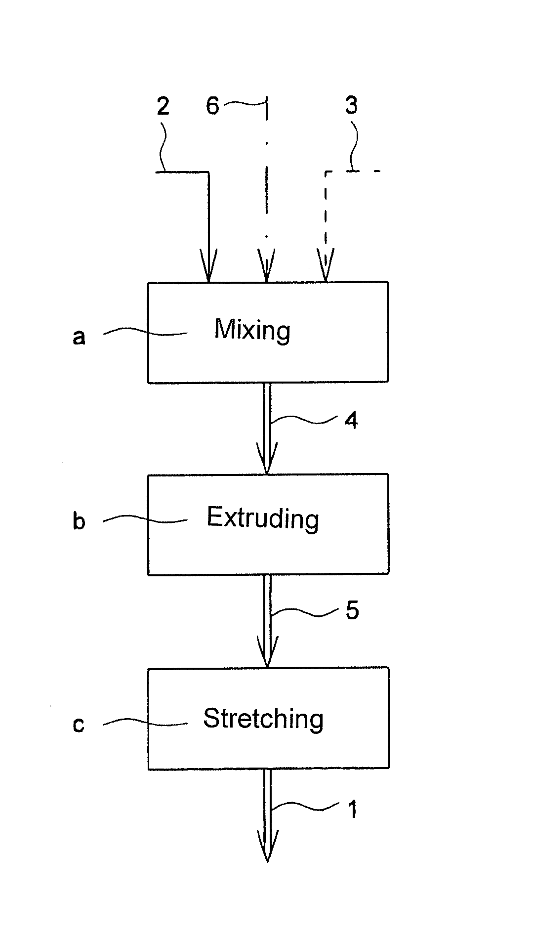
One drawback of this process is that the use of organic solvent is necessary, and the process comprises several process steps, which makes the production of membranes production-intensive and costly.
Moreover, the process is largely limited to the use of readily soluble polymers, such as PVDF or PSU.
The previously-described

Method used


Image

  • Method for the production of a filter membrane and filter membrane

Examples


example 1

[0040]LDPE was used as a polymer membrane material for the production of a polymer film. Chalk was admixed into the membrane material as filler with a mean particle diameter of approximately 2 μm. Then, the thus obtained mixture was extruded for forming the polymer film. The chalk content of the polymer film was 65% by weight, and the LDPE content was 35% by weight. The thickness of the polymer film was 90 μm. The polymer film was stretched by a factor of 4 at 85° C., and the thickness of the polymer film was then 25 μm. The flow rate of the polymer film at a pressure differential of 5 bar was 160 l / (m2h bar), and the permeate was free of turbidity.

example 2

[0041]LDPE was used as a polymer membrane material for the production of a polymer film. Mica was admixed into the membrane material as filler with a mean particle diameter of approximately 8.5 μm. Then, the thus obtained mixture was extruded for forming the polymer film. The mica content of the polymer film was 55% by weight, and the LDPE content was 45% by weight. The thickness of the polymer film was 150 μm. The polymer film was stretched by a factor of 3 at 110° C., and the thickness of the polymer film was then 50 μm. The flow rate of the polymer film at a pressure differential of 5 bar was 120 l / (m2h bar), and the permeate was free of turbidity.

example 3

[0042]PP was used as a polymer membrane material for the production of a polymer film. As filler with a mean particle diameter of approximately 5 μm, barium sulfate and calcium sulfate were admixed into the membrane material. Then, the thus obtained mixture was extruded for forming the polymer film. The barium sulfate content of the polymer film was 25% by weight, the calcium sulfate content of the polymer film was 25% by weight, and the PP content was 50% by weight. The thickness of the polymer film was 100 μm. The polymer film was stretched by a factor of 3.5 at 110° C., and the thickness of the polymer film was then 30 μm. The flow rate of the polymer film at a pressure differential of 5 bar was 200 l / (m2h.bar), and the permeate was free of turbidity.


PUM

PropertyMeasurementUnit
Temperatureaaaaaaaaaa
Percent by massaaaaaaaaaa

Abstract

A method for the production of a filter membrane (1), whereby as starting material for the membrane production, at least one filler (3) and, optionally, at least one additional aggregate are admixed into a polymer membrane material (2), whereby the membrane material (4) that has the filler (3), and optionally the additional aggregate, is extruded to form a polymer film (5) that is charged with the filler (3), and optionally, the additional aggregate, after which the polymer film (5) is then stretched in a particularly monoaxial and/or biaxial manner for pore formation.

Description

BACKGROUND OF THE INVENTION[0001]1. Field of the Invention[0002]The invention relates to a method for the production of a filter membrane and a filter membrane that can be obtained in accordance with the method according to the invention.[0003]2. Description of Related Art[0004](Micro-)porous filter membranes are used in a host of fields of industrial, pharmaceutical or medical applications for precision filtration. In these applications, membrane based separation processes are gaining increasing importance since these processes offer the advantage that the substances to be separated are not heat-stressed or even damaged. For example, microfiltration membranes make it possible to remove fine particles or microorganisms with sizes of up to the submicron range and are therefore suitable, for example, for the production of purified water for use in laboratories or for the semiconductor industry. Numerous other applications of membrane based separation processes are known from the bever...

Claims


Application Information

Patent Timeline
IPC IPC(8): B01D71/26B01D67/00B29D99/00B01D69/12
CPCB01D71/26B01D69/12B01D67/0088B29D99/005B29K2105/0005B29K2023/12B29K2023/0625B29K2105/0088B29K2509/00B29K2023/0633B01D67/0079B01D69/148B01D2323/21
Inventor SCHROER, JORNPLACKE, DANIEL
Owner EWALD DORKEN
Why Eureka
Try Eureka