Magnetic body and electronic component using the same

a technology of electronic components and magnetic bodies, applied in the direction of magnetic bodies, magnetic materials, inorganic material magnetism, etc., can solve the problem of limiting the size of components, and achieve the effect of less plating elongation, high insulation property and high-precision forming

Active Publication Date: 2015-03-26
TAIYO YUDEN KK
View PDF6 Cites 5 Cited by
  • Summary
  • Abstract
  • Description
  • Claims
  • Application Information

AI Technical Summary

Benefits of technology

[0008]In light of the above, an object of the present invention is to provide a new magnetic body that can improve both the insulation resistance and filling property, as well as an electronic component using such magnetic body.
[0020]According to the present invention, a magnetic body is provided that offers higher insulation property because sulfur has been added, and thus allows for high-precision forming of electrodes with less plating elongation, even when directly-coupled electrodes are formed. Since the compacting density can be increased while maintaining the same insulation property, the magnetic permeability is expected to improve during heat treatment, which consequently helps reduce the size of the electronic component. It has been confirmed that adding sulfur leads to a manifestation of magnetic permeability improvement effect even at low heat treatment temperatures. Accordingly, a smaller amount of heat is required for heat treatment and therefore the holding time can be reduced while maintaining the same heat treatment temperature, for example, which is expected to lead to a shorter heat treatment time and consequently higher productivity.

Problems solved by technology

According to the art described in each of the above patent literatures, however, the glass or oxide film must be made sufficiently thick in order to ensure insulation property, which presents an impediment to improving the filling property and consequently limits how much the component size can be reduced.

Method used


Image

  • Magnetic body and electronic component using the same
  • Magnetic body and electronic component using the same

Examples


Embodiment Construction

[0025]The present invention is described in detail by referring to the drawing as deemed appropriate. It should be noted, however, that the present invention is not limited to the embodiment illustrated in any way, and that the scale of each part of the drawing is not necessarily accurate as characteristic parts of the invention may be exaggerated in the drawing.

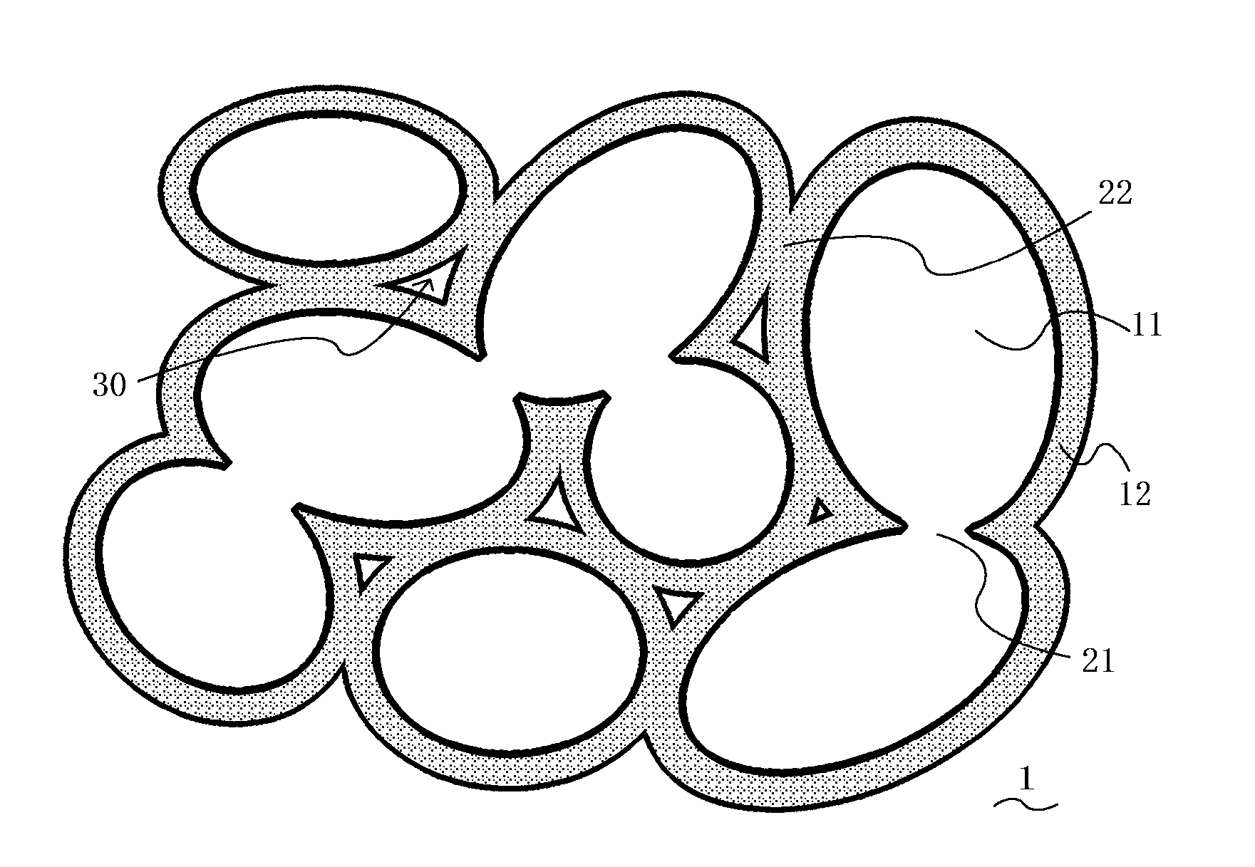
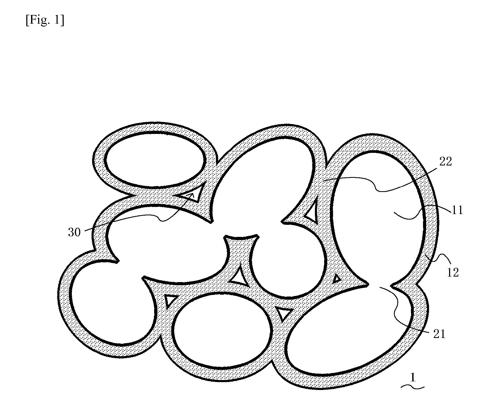
[0026]FIG. 1 is a section view providing a schematic representation of the detailed structure of the magnetic body proposed by the present invention. Under the present invention, a magnetic body 1 is understood, microscopically, as an aggregate of many magnetic grains 11 that bond together but were originally independent, where the individual magnetic grains 11 have oxide film 12 formed almost all around them and this oxide film 12 ensures the insulation property of the magnetic body 1. Adjacent magnetic grains 11 primarily or predominantly bond together via the oxide film 12 present around these magnetic grains 11, thereby ...


PUM

PropertyMeasurementUnit
apparent densityaaaaaaaaaa
sizeaaaaaaaaaa

Abstract

A magnetic body constituted by magnetic grains bonded together via oxide film, which magnetic grains contain a Fe—Si-M soft magnetic alloy (where M is a metal element more easily oxidized than Fe) that contains sulfur atoms (S). The magnetic body preferably contains 0.004 to 0.012 percent by weight of S, 1.5 to 7.5 percent by weight of Si, and 2 to 8 percent by weight of metal M.

Description

FIELD OF THE INVENTION[0001]The present invention relates to a magnetic body that can be used primarily as a magnetic core of a coil, inductor or other electronic component, as well as an electronic component using such magnetic body.DESCRIPTION OF THE RELATED ART[0002]Inductors, choke coils, transformers, and other electronic components (so-called “coil components / inductance components”) have a magnetic body constituting their magnetic core, as well as a coil formed in or on the surface of the magnetic body. Ni—Cu—Zn and other types of ferrites are generally used as materials for such magnetic bodies.[0003]In recent years, electronic components of these types are facing a need for larger current (i.e., need to increase their rated current), and to meet this demand, producing their magnetic bodies from Fe—Cr—Si alloy instead of traditional ferrites is being considered. Materials such as Fe—Cr—Si alloy and Fe—Al—Si alloy have higher saturated magnetic flux densities compared to ferri...

Claims


Application Information

Patent Timeline
Patent Type & Authority Applications(United States)
IPC IPC(8): H01F1/147C22C38/06C22C38/34
CPCH01F1/14766C22C38/06C22C38/34H01F1/24H01F1/33B22F2998/10C22C2202/02C22C33/0257C22C33/0285
Inventor TANADA, ATSUSHITANAKA, KIYOSHI
Owner TAIYO YUDEN KK
Why Eureka
Try Eureka