
Dry type economizer

a technology of economizer and dry type, which is applied in the direction of transformer/react mounting/support/suspension, basic electric elements, electrical apparatus, etc., can solve the problems of reducing the efficiency of economizer, and reducing so as to achieve the effect of eliminating the use of insulating oil

Active Publication Date: 2015-03-26
SHUN FU TECH
View PDF6 Cites 2 Cited by
  • Summary
  • Abstract
  • Description
  • Claims
  • Application Information

AI Technical Summary

Benefits of technology

The present invention provides a dry type economizer that eliminates the use of insulating oil. It includes a plurality of bodies with silicon-steel layers and insulating layers. Each body has windings composed of a wire material with an increased diameters of -50% to 60% when compared to standard wire diameter of 3.5 mm. The increased volume provides a large surface area in contact with the atmosphere for quick dissipation of heat during operation of the reactance elements. The technical effects of this invention are that it eliminates the use of insulating oil, prevents degradation of internal components, and provides quick dissipation of heat during operation of the reactance elements.

Problems solved by technology

Thus, an economizer can make full use of clean, high-load electricity, saving electricity costs and prolonging equipment lifespan.
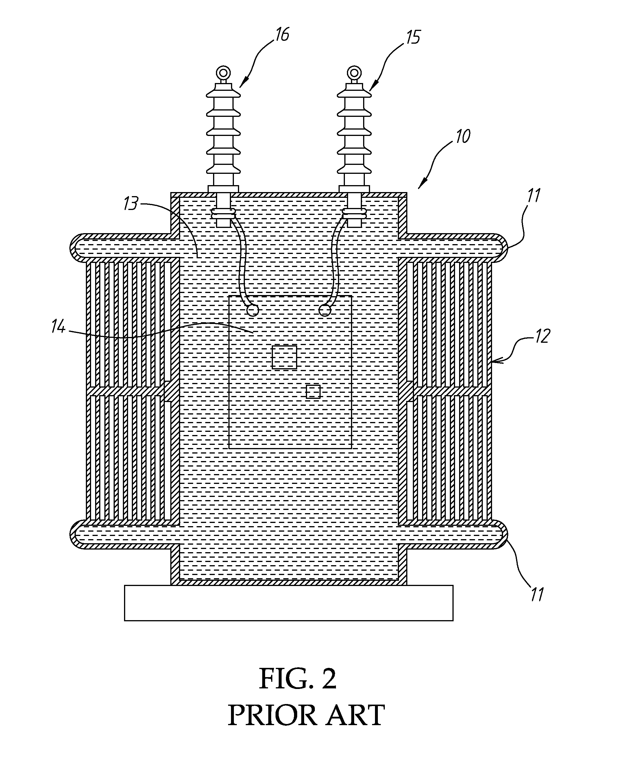
During operation of the reactance elements and switching devices, the electronic circuit will generate a large amount of heat, and therefore a cooling operation is necessary to lower the temperature.
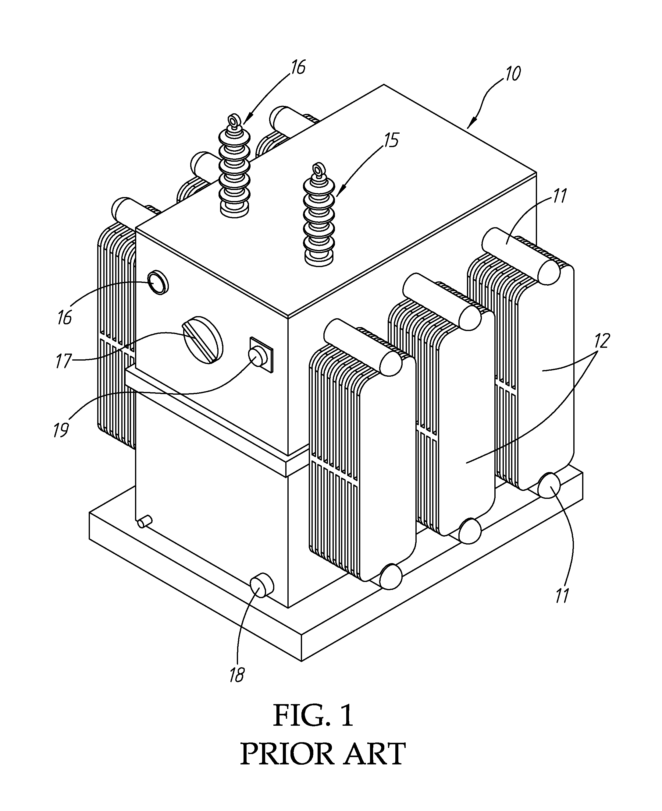
However, the use of the electrical insulating oil 13, drain valve 18 and oil level meter 19 greatly complicates the operation and control of the economizer.
The internal electrical insulating oil 13 can absorb oxygen and moisture from the air to produce grease stain, increasing the water content and causing components degradation.

Method used


Image

  • Dry type economizer
  • Dry type economizer
  • Dry type economizer

Examples


Embodiment Construction

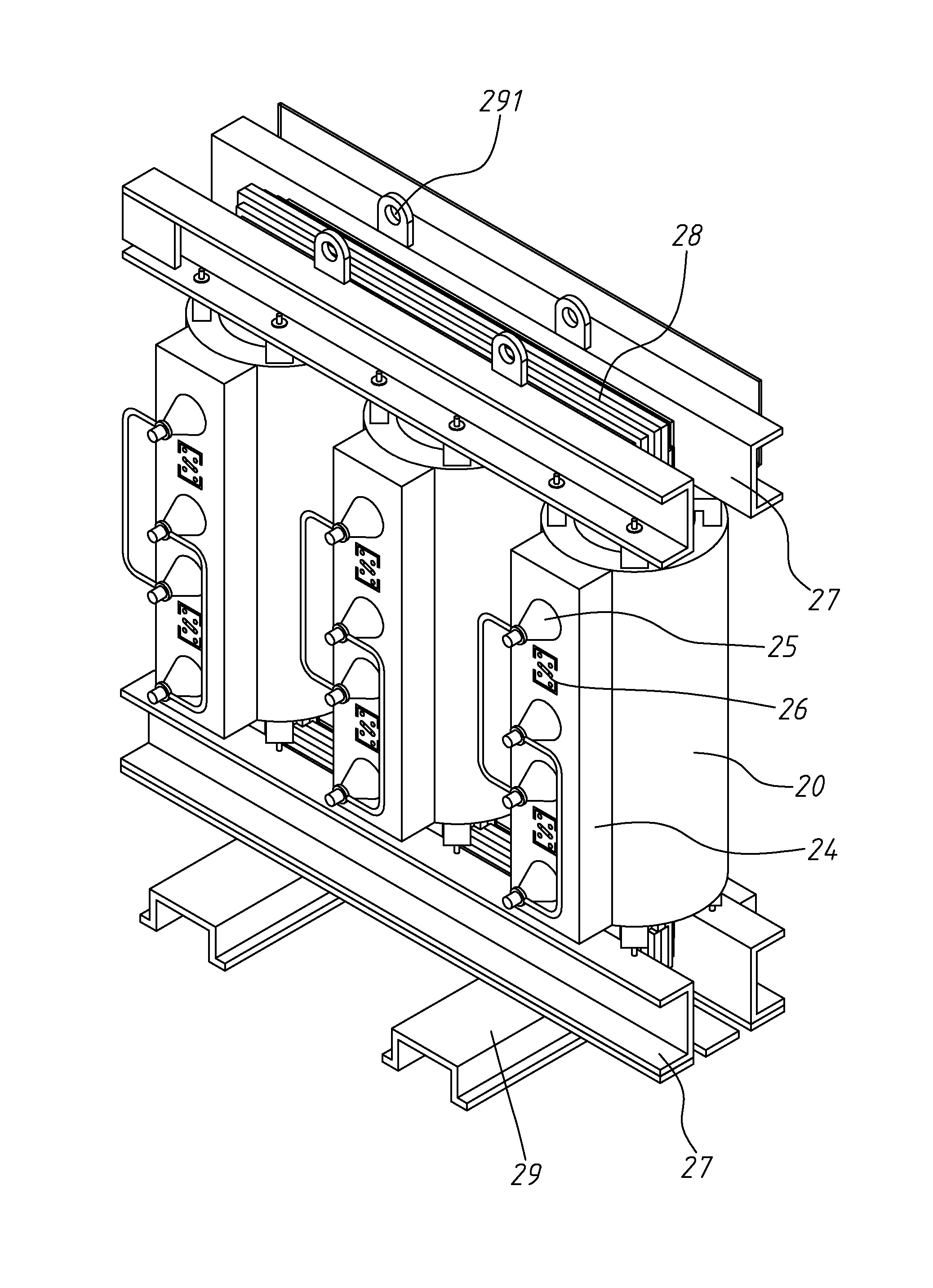
[0023]Referring to FIGS. 3 and 4, an economizing unit for dry type economizer in accordance with the present invention is shown. The economizing unit comprises a plurality of bodies 20 in a particular size. In this embodiment, the bodies 20 have a cylindrical shape to increase the surface contact area with the atmosphere. However, this cylindrical shape is for the purpose of illustration only, but not intended for use to restrict the claims of the invention.

[0024]Each body 20 comprises a silicon-steel layer 21, an insulating layer 22 surrounding the silicon-steel layer 21, and a plurality of windings 23 surrounding the insulating layer 22. The windings 23 are intended for use to energize reactance elements and reactance filter converters. The invention increases the wire diameter of the windings 23 to reduce resistance and heat. In most conventional economizers, a 3.5 mm wire material is used to make the winding. In this embodiment of the present invention, a 5.25 mm wire material i...


PUM


Abstract

A dry type economizer includes an economizing unit formed of a plurality of bodies, each body including a silicon-steel layer, an insulating layer surrounding the silicon-steel layer, a plurality of windings surrounding the insulating layer, and reactance elements and reactance filter converters respectively electrically connected to the windings, each winding being formed of a wire material having an increased wire diameter larger than a standard wire diameter of 3.5 mm. Thus, each body eliminates the use of any insulating oil, and has an increased volume to provide a large surface area in contact with the atmosphere for quick dissipation of heat during operation of the reactance elements.

Description

BACKGROUND OF THE INVENTION[0001]1. Field of the Invention:[0002]The present invention relates to economizers for power-supply optimization, and more particular, to a dry type economizer, which eliminates the use of any insulating oil for heat dissipation, preventing component degradation.[0003]2. Description of the Related Art:[0004]An economizer is a mechanical device to be used for power-supply optimization during power conversion for energy efficiency. An economizer eliminates excess electricity by: absorbing reactive power through a reactance effect, restricting the access point over-voltage, removing noises and harmonic waves from the delivering power supply to eliminate unnecessary electromagnetic induction. Thus, an economizer can make full use of clean, high-load electricity, saving electricity costs and prolonging equipment lifespan.[0005]In the reactance filter circuit structure of a conventional economizer, multi-stage switching devices are used for controlling different...

Claims


Application Information

Patent Timeline
IPC IPC(8): H01F27/28H01F27/06
CPCH01F27/06H01F27/2876H01F27/306
Inventor YOU, MING-SHUNCHOU, HUAN-YU
Owner SHUN FU TECH
Learn More