Method and apparatus for monitoring a condition of an operating implement in heavy loading equipment

a technology for operating implements and equipment, applied in the field of image processing, can solve problems such as safety hazards, damage to downstream equipment for processing, and wear and/or damage of teeth and/or adapters during operation, and achieve the effect of preventing damage to image sensors

Inactive Publication Date: 2015-03-26
MOTION METRICS INT CORP
View PDF9 Cites 53 Cited by
  • Summary
  • Abstract
  • Description
  • Claims
  • Application Information

AI Technical Summary

Benefits of technology

[0052]The image sensor may be disposed on the heavy equipment below the operating implement and may further include a shield disposed above the image sensor to prevent damage to the image sensor by falling debris from a material being operated on by the operating implement.

Problems solved by technology

The teeth and / or adapters may become worn, damaged, or detached during operation.
In a mining operation, a detached tooth and / or adapter may damage downstream equipment for processing the ore.
An undetected broken tooth and / or adapter from a loader, backhoe, or mining shovel can also cause safety risk since if the tooth enters an ore crusher, for example, the tooth may be propelled at a very high speed due to rotation of the crusher blades thus presenting a potentially lethal safety risk.
In some cases the tooth may become stuck in the downstream processing equipment such as the crusher, where recovery causes downtime and represents a safety hazard to workers.
The broken tooth may also pass through the crusher and may cause significant damage to other downstream processing equipment, such as for example longitudinal and / or lateral cutting of a conveyor belt.
There remains a need for monitoring systems for other heavy equipment such as front-end loaders, wheel loaders, bucket loaders, and backhoe excavators, which do not provide a convenient location that has an unobstructed view of the operating implement during operations.

Method used


Image

  • Method and apparatus for monitoring a condition of an operating implement in heavy loading equipment
  • Method and apparatus for monitoring a condition of an operating implement in heavy loading equipment
  • Method and apparatus for monitoring a condition of an operating implement in heavy loading equipment

Examples


Embodiment Construction

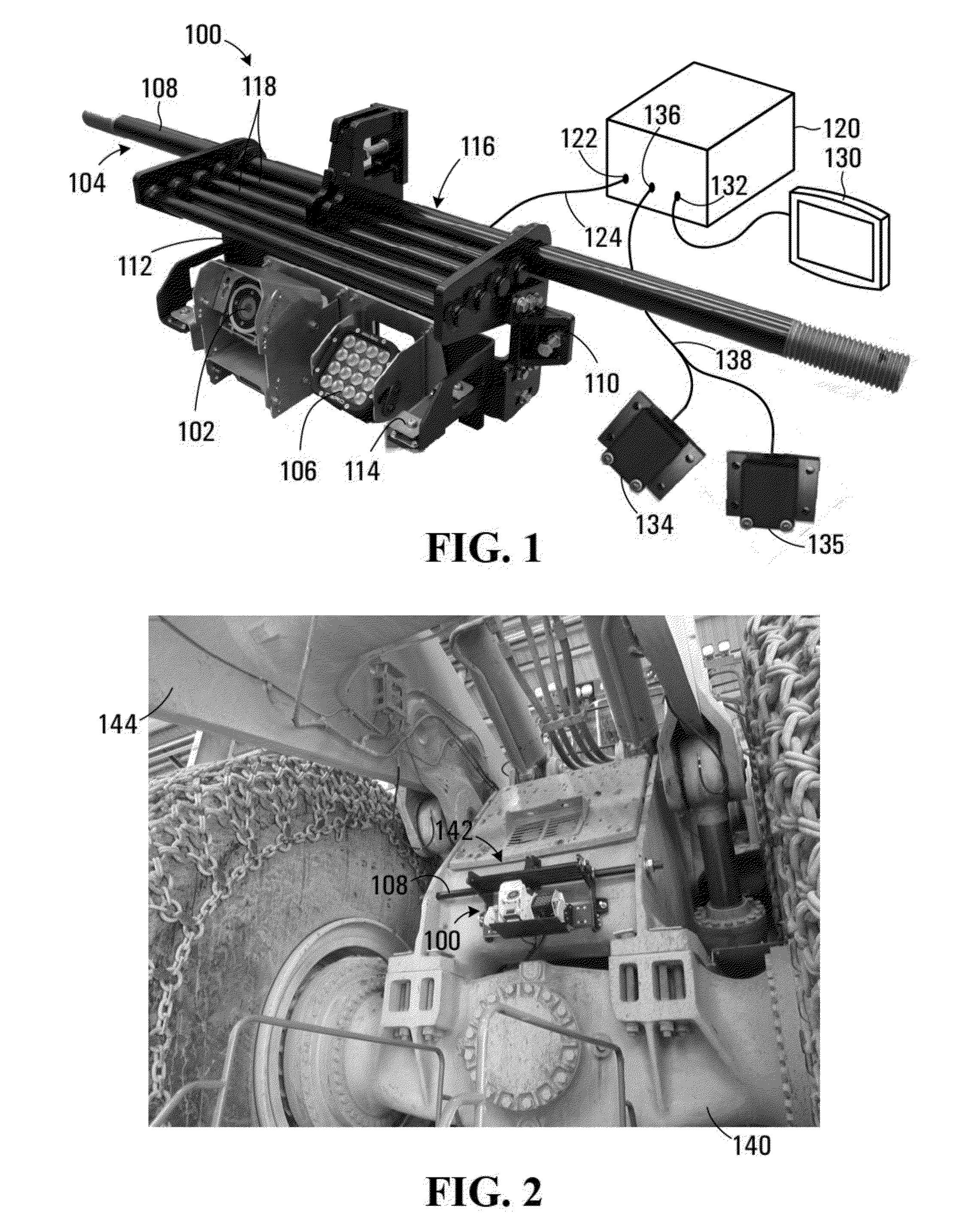
[0077]Referring to FIG. 1, an apparatus for monitoring a condition of an operating implement in heavy equipment according to a first embodiment of the invention is shown generally at 100. The apparatus 100 includes an image sensor 102 mounted on a bracket 104. In the embodiment shown the apparatus 100 also includes an illumination source 106 mounted on the bracket 104 for illuminating a field of view of the image sensor 102. The apparatus 100 may also include one or more motion sensors 134 and 135. In this embodiment the motion sensors 134 and 135 are inertial sensors, which may include accelerometers, gyroscopes, and magnetometers for generating orientation signals.

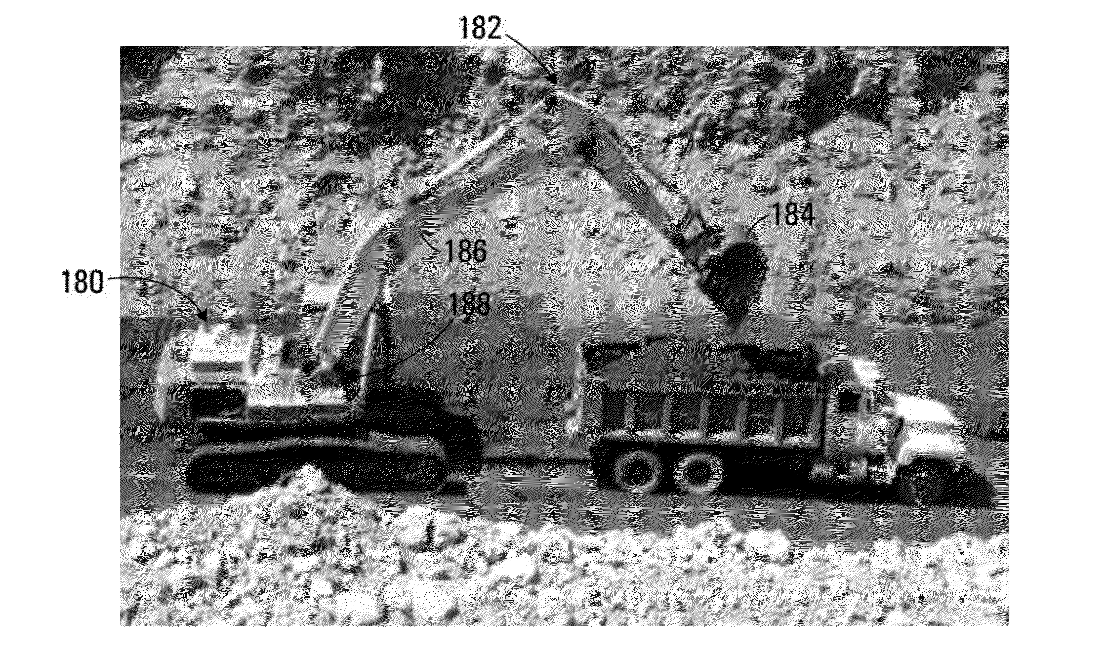
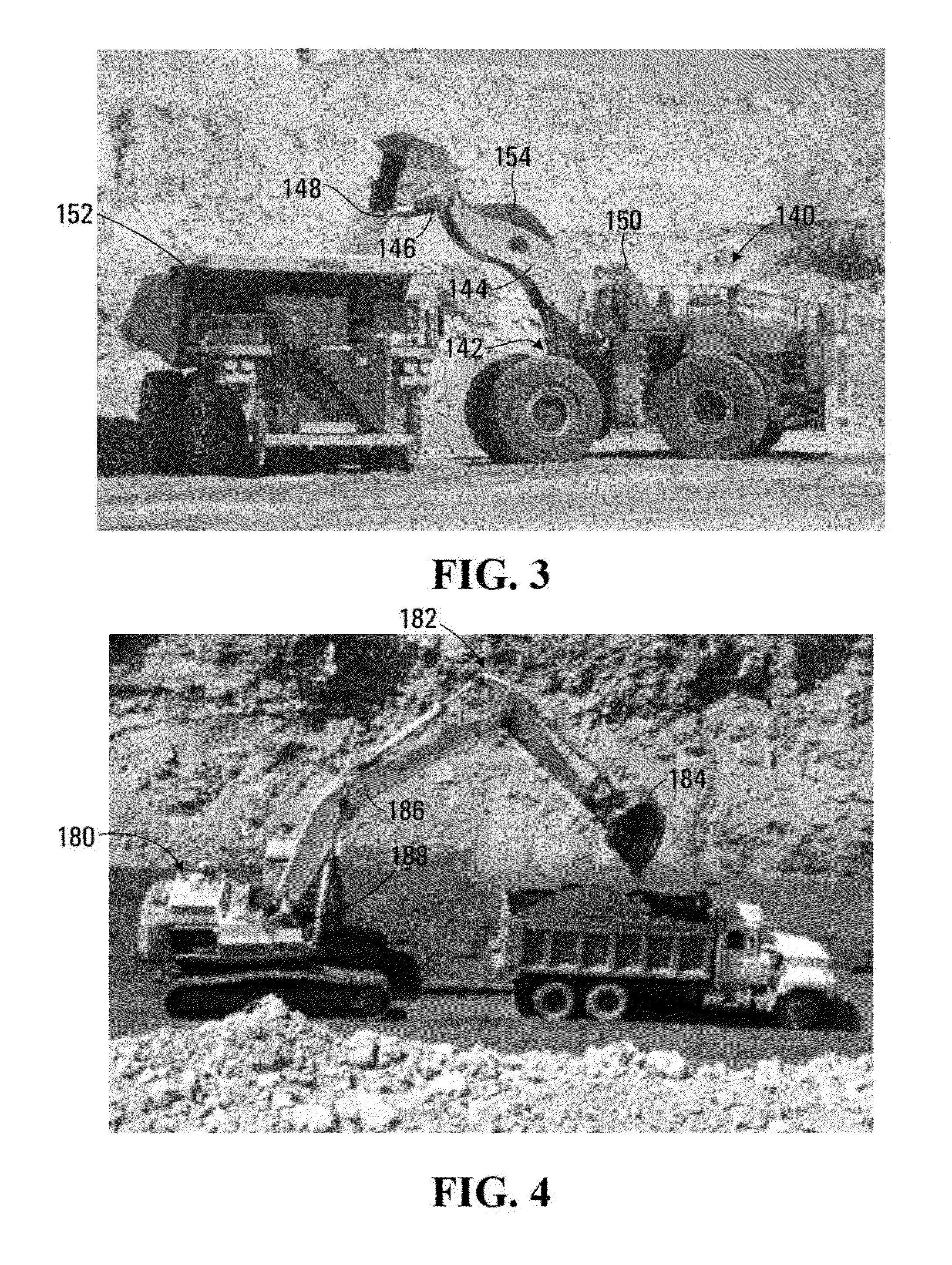
[0078]Referring to FIG. 2, in one embodiment the apparatus 100 is mounted on a wheel loader 140 at a mounting location 142 under a boom 144 of the loader. Referring to FIG. 3, the wheel loader 140 includes an operating implement 146, which for a loader is commonly referred to as a bucket. The operating implement 146 is c...


PUM

PropertyMeasurementUnit
distanceaaaaaaaaaa
thermalaaaaaaaaaa
temperatureaaaaaaaaaa

Abstract

A method and apparatus for monitoring a condition of an operating implement in heavy equipment is disclosed. The method involves receiving a trigger signal indicating that the operating implement is within a field of view of an image sensor, and in response to receiving the trigger signal, causing the image sensor to capture at least one image of the operating implement. The method also involves processing the at least one image to determine the condition of the operating implement. A visual or audio warning or alarm may be generated for preventing significant damage to the processing equipment and avoid safety hazards involved.

Description

BACKGROUND OF THE INVENTION[0001]1. Field of Invention[0002]This invention relates generally to image processing and more particularly to processing of images to monitor a condition of an operating implement in heavy equipment.[0003]2. Description of Related Art[0004]Heavy equipment used in mining and quarries commonly includes an operating implement such as a bucket or shovel for loading, manipulating, or moving material such as ore, dirt, or other waste. In many cases the operating implement has a sacrificial Ground Engaging Tool (GET) which often include hardened metal teeth and adapters for digging into the material. The teeth and / or adapters may become worn, damaged, or detached during operation. Wear in the implement is natural due to its contact with often abrasive material and is considered a sacrificial component which serves to protect the longer lasting parts of the GET.[0005]In a mining operation, a detached tooth and / or adapter may damage downstream equipment for proces...

Claims


Application Information

Patent Timeline
Patent Type & Authority Applications(United States)
IPC IPC(8): G01M99/00H04N7/18G01N21/84
CPCG01M99/005H04N7/188G01N21/84G01S13/06G01S13/865G01S13/867G01S17/06G01S17/86G01S17/89
Inventor TAFAZOLI BILANDI, SHAHRAMPARNIAN, NEDABAUMANN, MATTHEW ALEXANDERRADMARD, SINA
Owner MOTION METRICS INT CORP
Why Eureka
Try Eureka